Clutch and Transmission – Check!
The 'old' clutch package that was bolted to the flywheel was in question due to some linkage geometry issues. And, well, it was used, and unknown, and had to come out anyway because of our transmission input shaft swap with a different spline count.
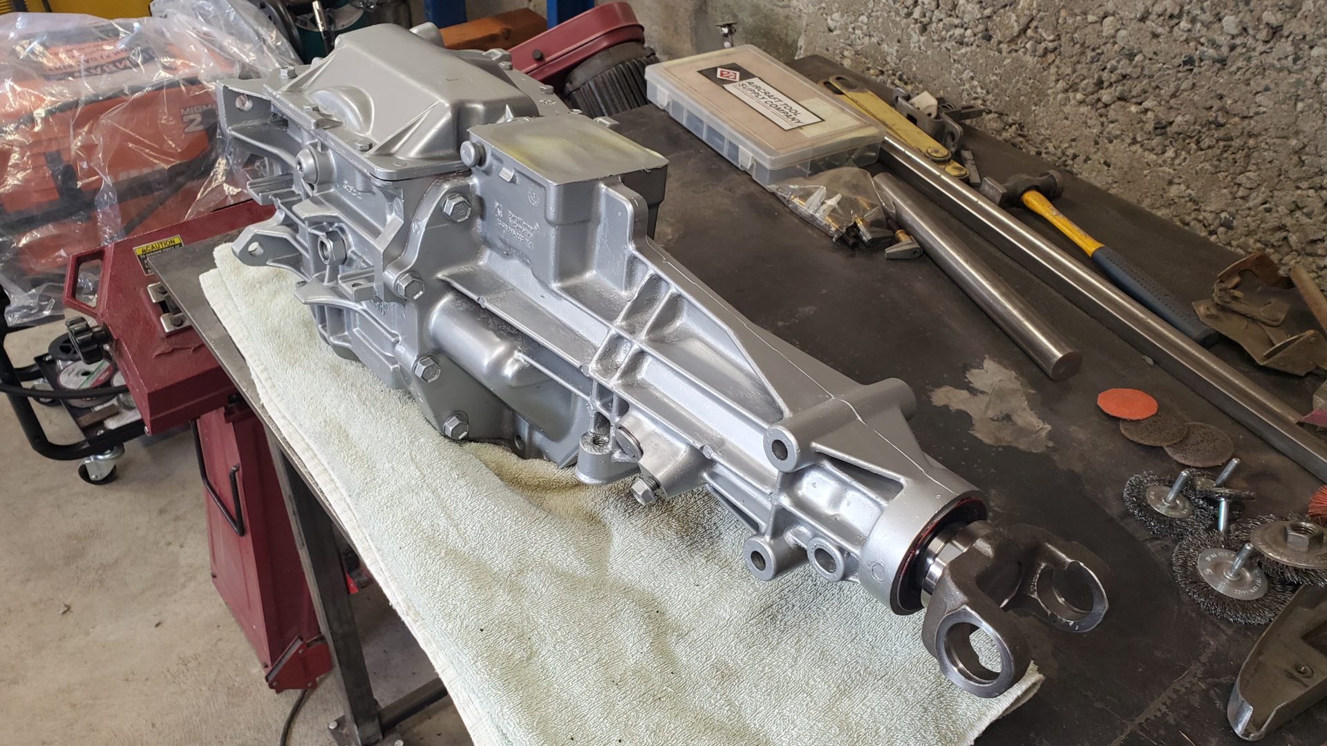
As mentioned in the last post we found rust inside the T-5 transmission. Some of it was light surface staining but other corrosion was crusty and scaly. Beneath the scale there was light pitting. That's not what you want find on gear teeth. Other parts were completely unscathed and in good shape.
While this is far from ideal, it doesn’t mean the transmission won’t work. It just means it might BE noisy, or BECOME noisy with time, or some other failure could EVENTUALLY occur.
If you're at all OCD or particular about doing things 'right', this kind of stuff is hard to turn a blind eye to. But, budgets are limited. So, we informed the customer and suggested that rather than spend a bunch of money, we clean it up best we could, put it back together, and see what happens. If there was problem or one developed, the transmission is easy enough to take out. The customer agreed.
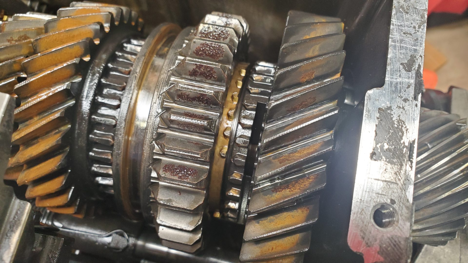
We tore the case down for a much needed cleaning. The magnet in the bottom of the case was covered in a metallic sludge. Virtually all the gears inside had some corrosion. We dropped them into a container of Rust911 which, ironically, is water based and let it do its voodoo magic. It handily removed the rust.
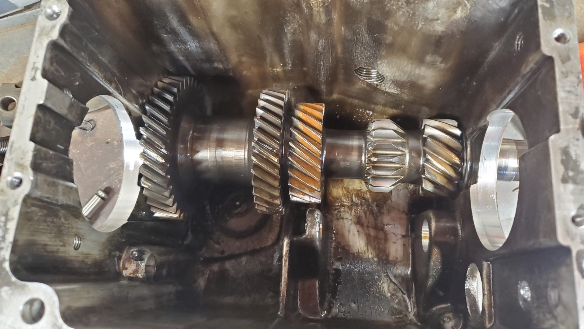
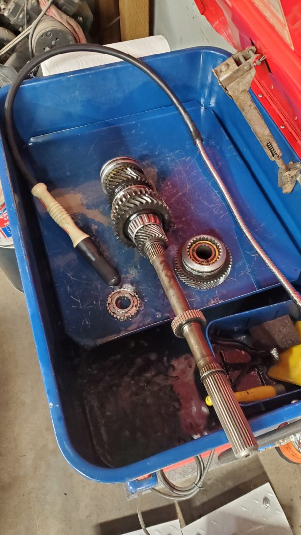
While not doing a full rebuild, most bearings, a couple of synchros, seals, and other small parts were replaced from a kit along with the input shaft.
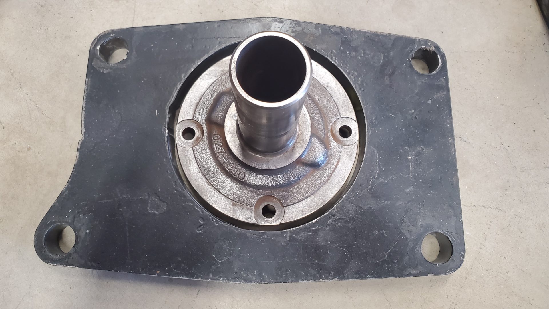
About 1/2" of the new 10 spline Jeep input shaft tip was cut off and the front bearing retainer shortened to expose more of the splines. The large, round edge of the retainer is what centers and aligns the transmission to the engine. The clutch release or throwout bearing slides front to rear on the tubular part of the retainer.
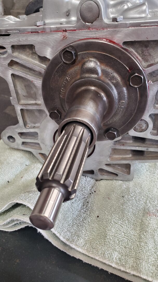
The input shaft/bearing retainer is what aligns the transmission to the bellhousing and engine. The hole in someone's home made spacer was way too big and would never have aligned the transmission correctly to the bellhousing and engine. Some precision is required. Misalignment here could result in poor performance or even catastrophic failure. The spacer is being ditched.
The input shaft/bearing retainer on the transmission is supposed to fit into hole on the bellhousing bolted to the back of the engine (below).
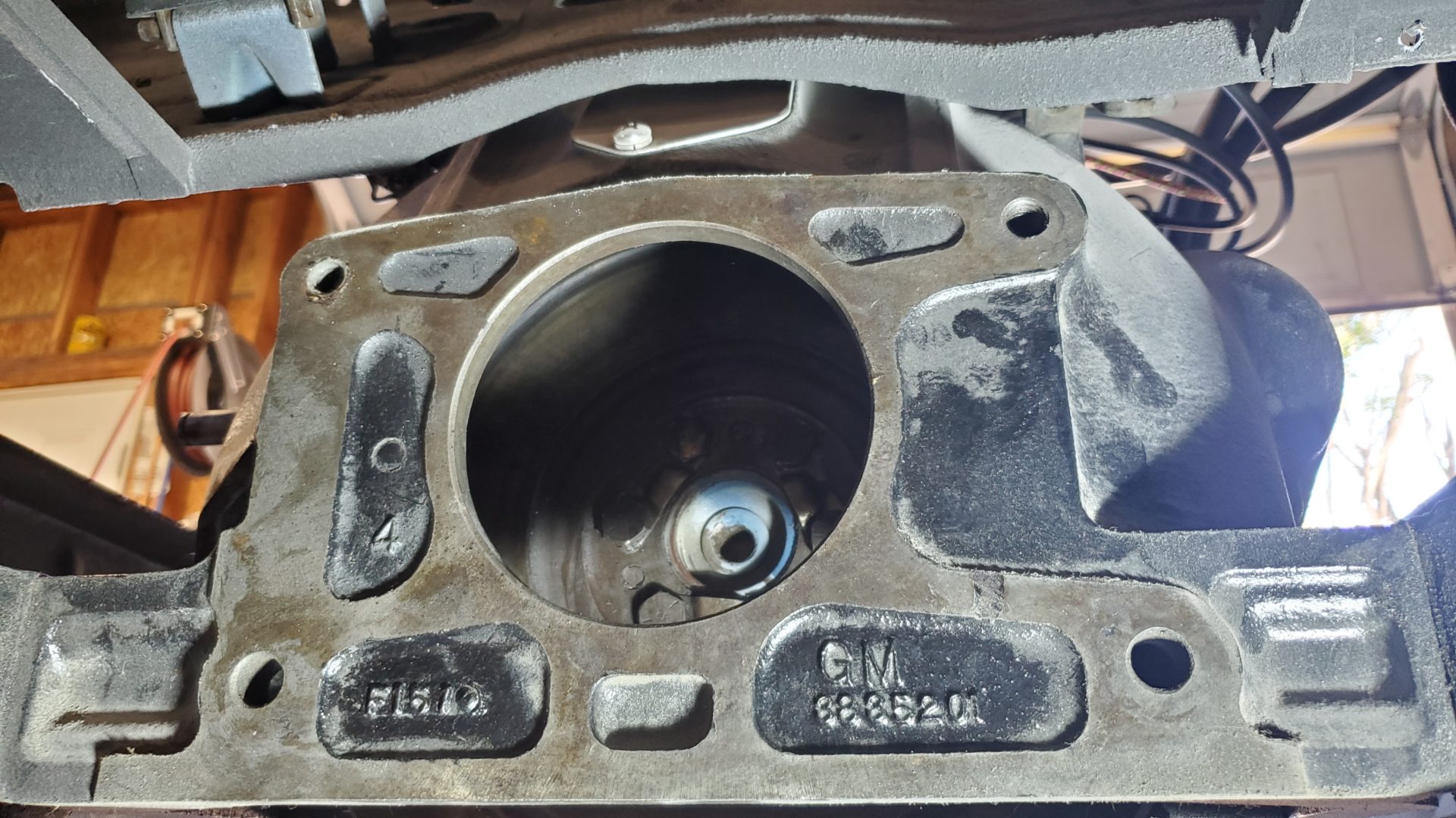
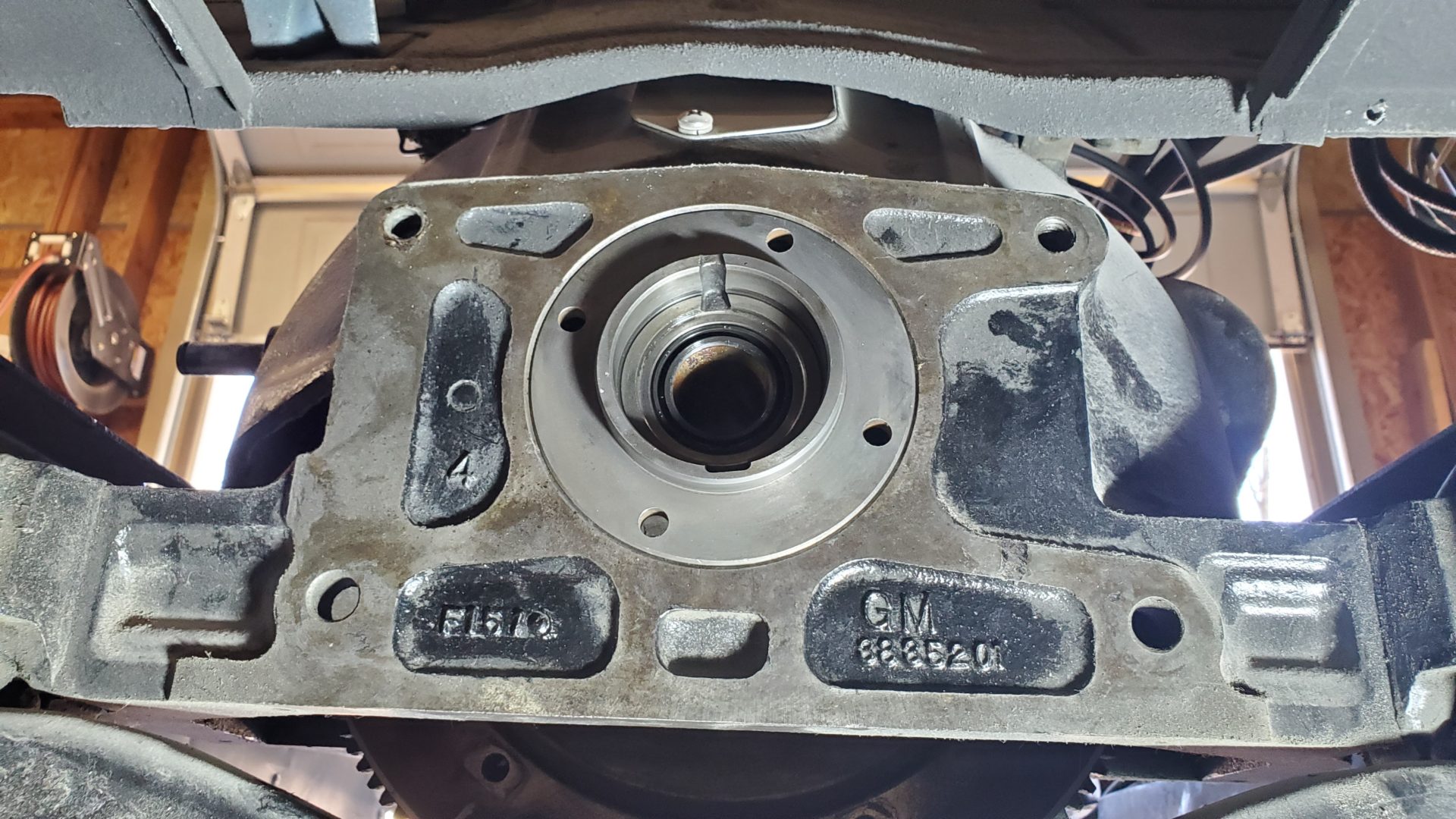
Taking the time to identify what we're working with by the casting numbers on the engine, bell housing, and flywheel paid off - saving time and frustration.
There is a pilot bushing pressed into the back of the engine crankshaft that the tip of the transmission input shaft fits into. It supports the shaft and allows it to spin. The new clutch package we ordered includes a new bushing. The new bushing would have been fine if this were an original 216 or 235 cubic inch truck engine, but it isn't.
This is a 1961 235 ci. car engine that came from the factory with a Powerglide automatic transmission. Back in the day, GM didn't machine those engine crankshafts for a manual transmission pilot bushing. There's a hole, but it's smaller - .030" smaller! (You can see the bushing a couple of photos back with some blue paint on it)
Thirty thousandths of an inch might not sound like much but it might as well be a mile when trying to drive a steel (not soft bronze) bushing into the hole. Luckily, we didn't have to find out the hard way.
Dorman makes (or made) a "conversion" pilot bushing for installing manual transmissions behind GM inline 6 engines that originally came with Powerglides. And yes, the outside diameter of the bushing is .030" smaller (1.065" vs 1.095"). Miracle of miracles, our local O'Reilly Auto parts had some on the shelf in back so we didn't have to order one. The Dorman part number is 690-034.
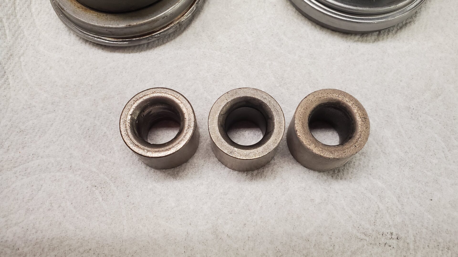
We used the ol' "shove bread or grease (we used a soft hot dog bun) into the hole and then hammer a rod (or old input shaft) in to 'hydraulically' extract the bushing" trick to get the old one out. Sounds weird but works great.
The old bushing was chewed up on the inside from a previous installation. The new bushing went in the freezer to shrink it slightly and then, using a hammer, driven into the crank - first with the old transmission input shaft as a tool to start and guide it, then a socket and extension to set the depth.
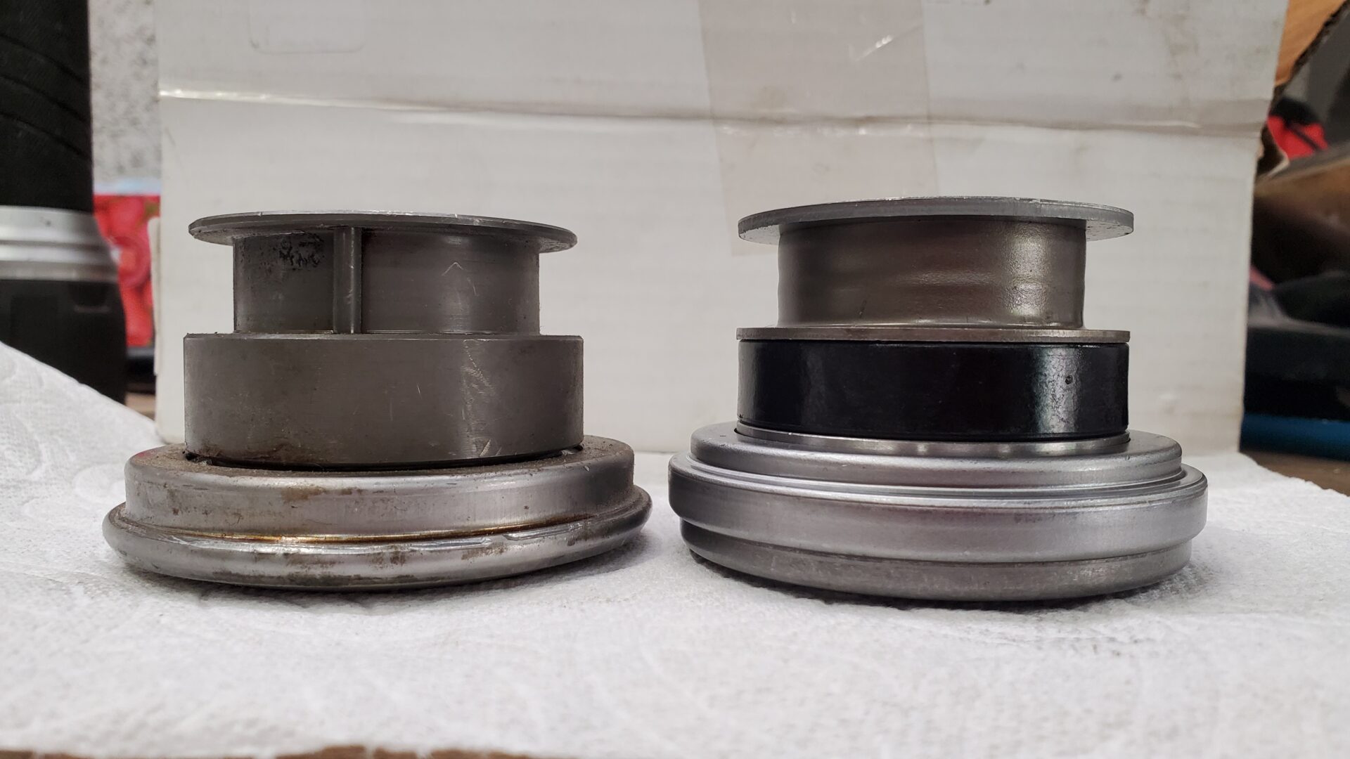
The new release bearing is slightly taller (or thicker) but not a problem.
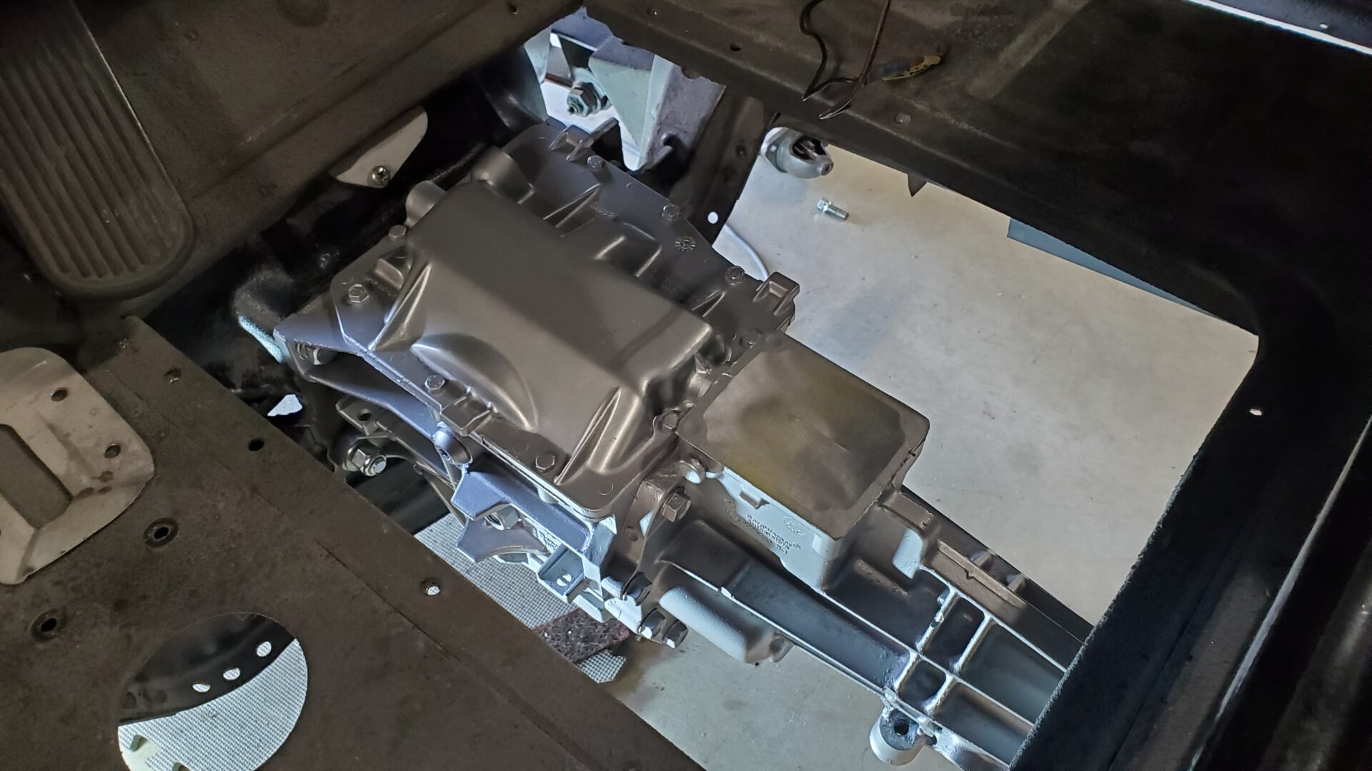
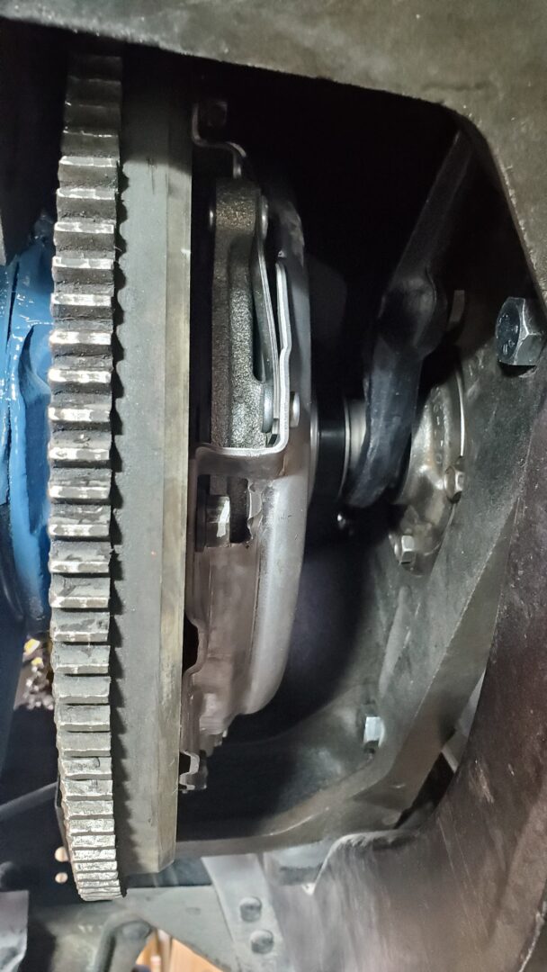
The new 9.125" clutch disc and pressure plate (part number MU1042-1) were bolted to the flywheel and the trans mated to the bell housing.
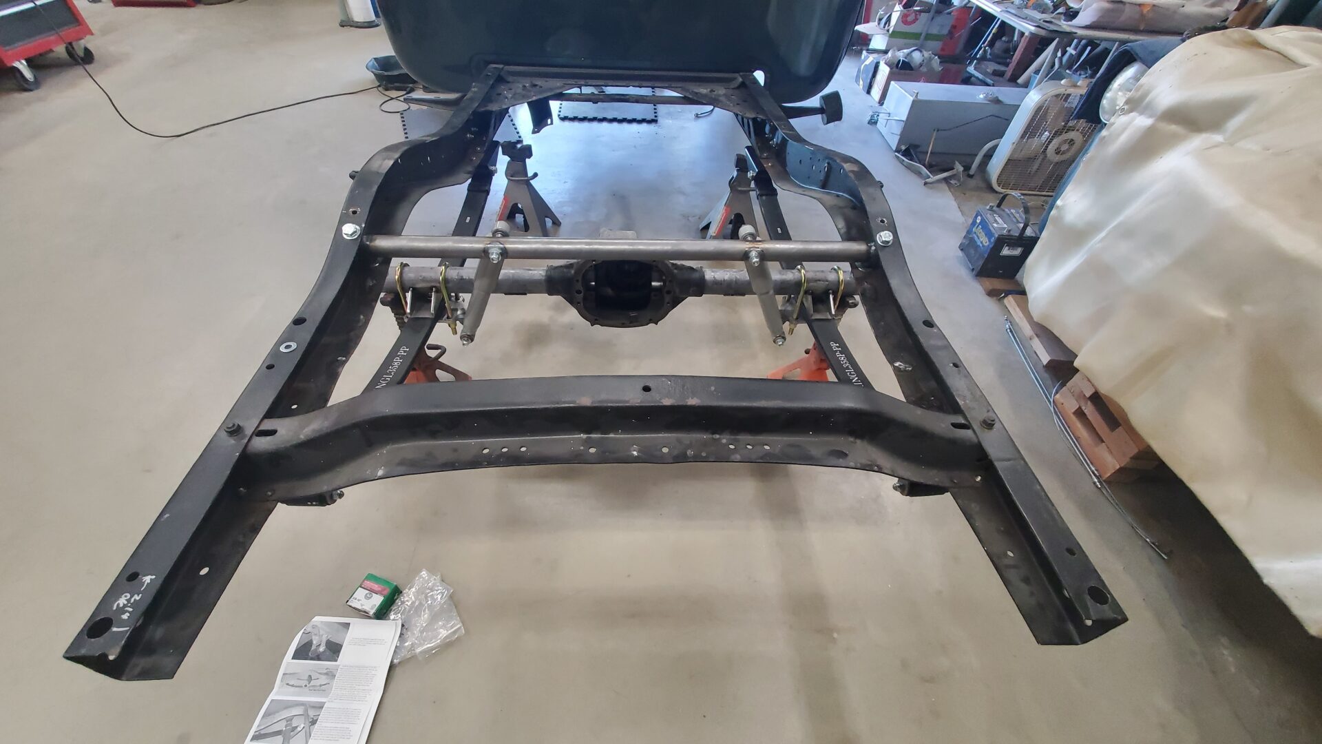
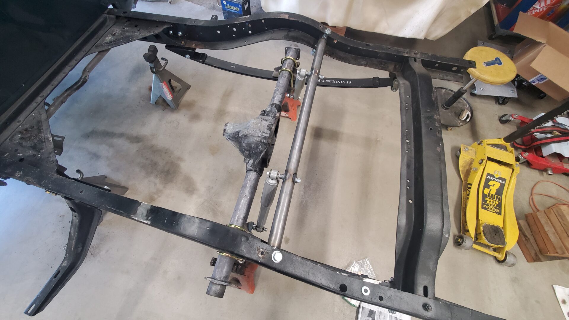
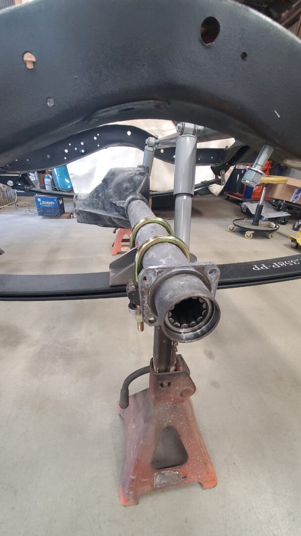
Now we can turn our attention again to the new rear suspension. Here, everything is mocked up for fit including the shock absorbers.
It can now be taken apart for some final welding, paint, and reassembly.
Stay tuned!
