Taming Spaghetti and More…
In our last post we had started installing a new wiring harness. The old one wasn't original, in fact it as a nice little 12-circuit kit from Speedway Motors. Unfortunately the fuse block was broken, it had been hacked and spliced numerous times, and was mostly hard-wired to everything. And, it could have used a few more circuits. I started over with a 28 circuit kit from Painless Performance. Yes, there were a few more circuits than what we needed (like power windows and door locks) but it's very nice and complete for a universal wiring harness.
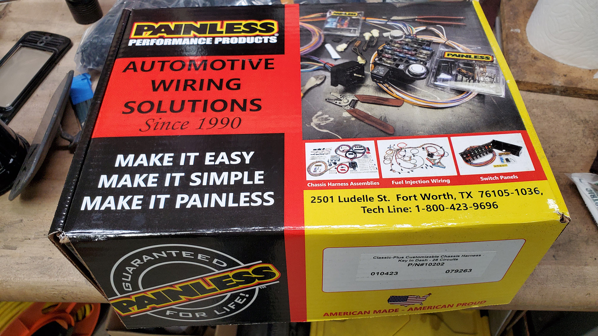
Painless does some sorting and organizing of the wiring for you into sections such as front lighting, engine, etc. but I spent time on the living room rug doing some additional sorting and changes as needed. Some unneeded wiring was removed to make it even more manageable. Not to worry. There's a 136 page instruction manual included that covers all kinds of scenarios.
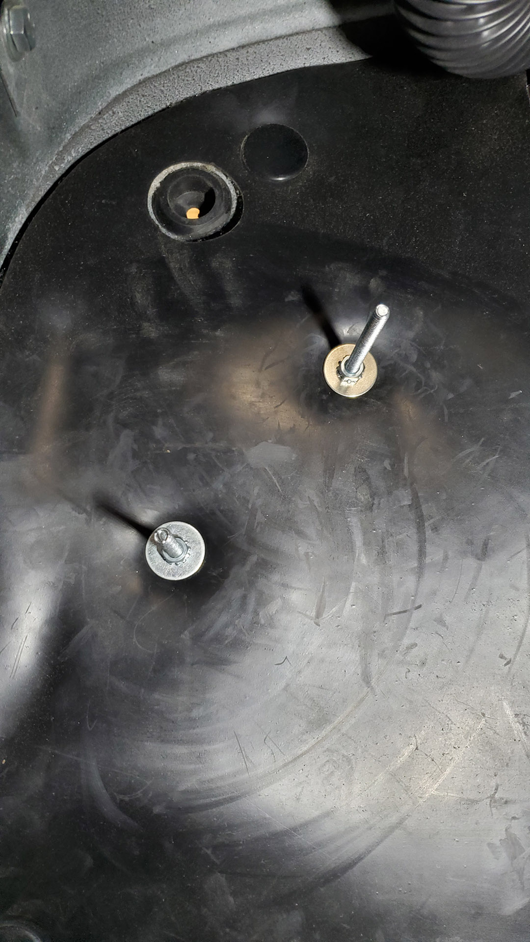
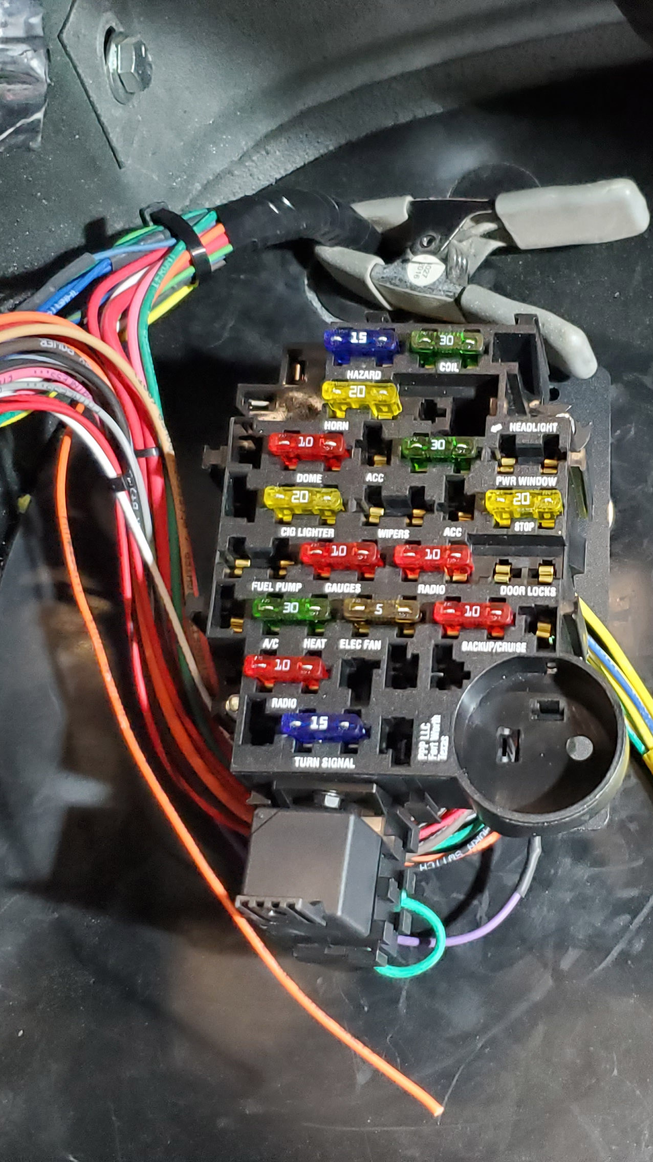
The first step was to get the fuse panel installed on the firewall. I came up with a stud arrangement so that the box could be easily removed. Next, with the box hung, bundles of wires that needed to exit the cab were fed through the original grommet hole. Wires that stay in the cab were routed to the left and would eventually pass behind the dash along the lower edge. Everything is or will be wrapped in harness tape, which is a non-sticky vinyl wrap. It looks good, keeps things organized, and doesn't create a sticky mess like electrical tape eventually does.
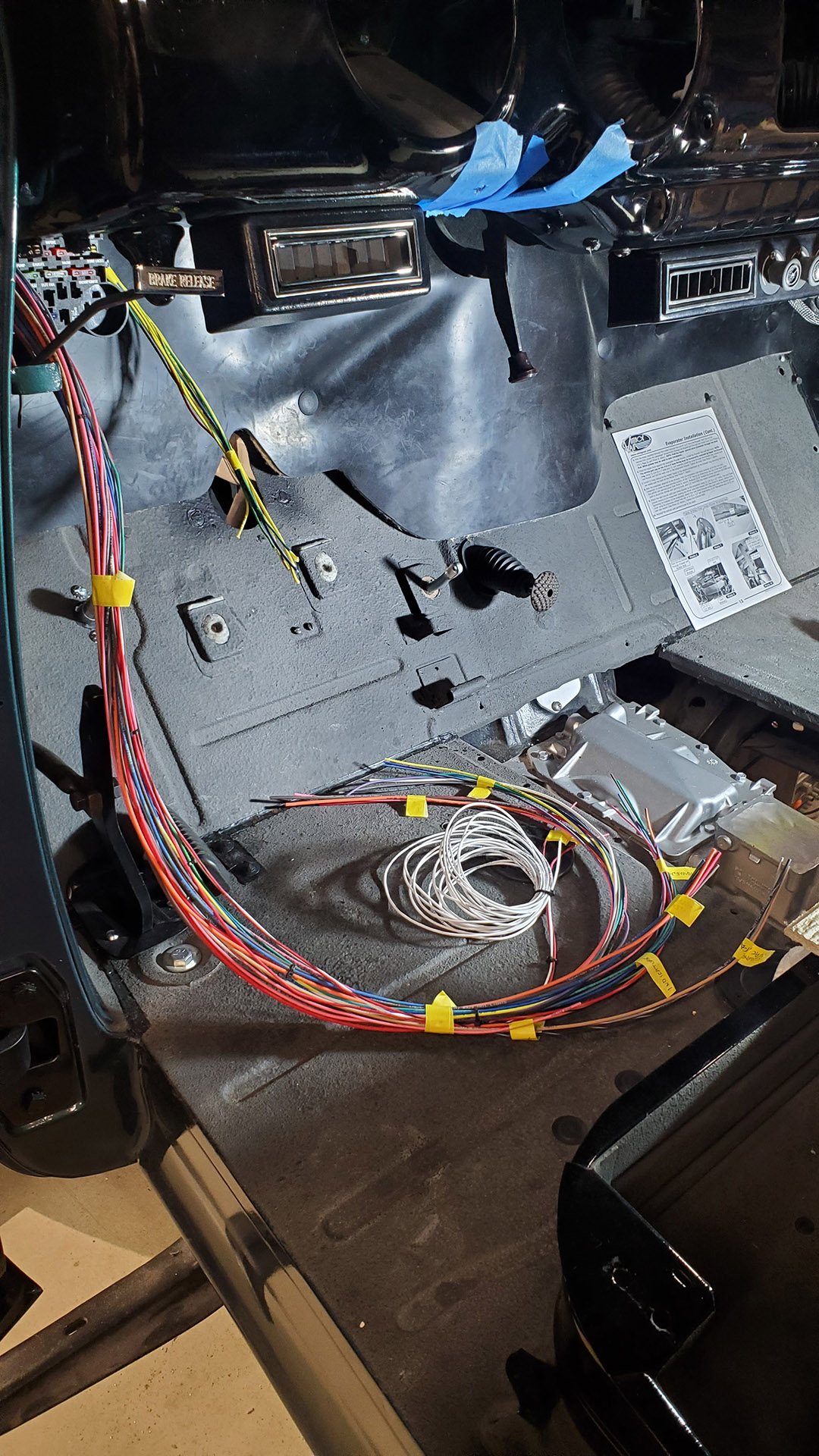
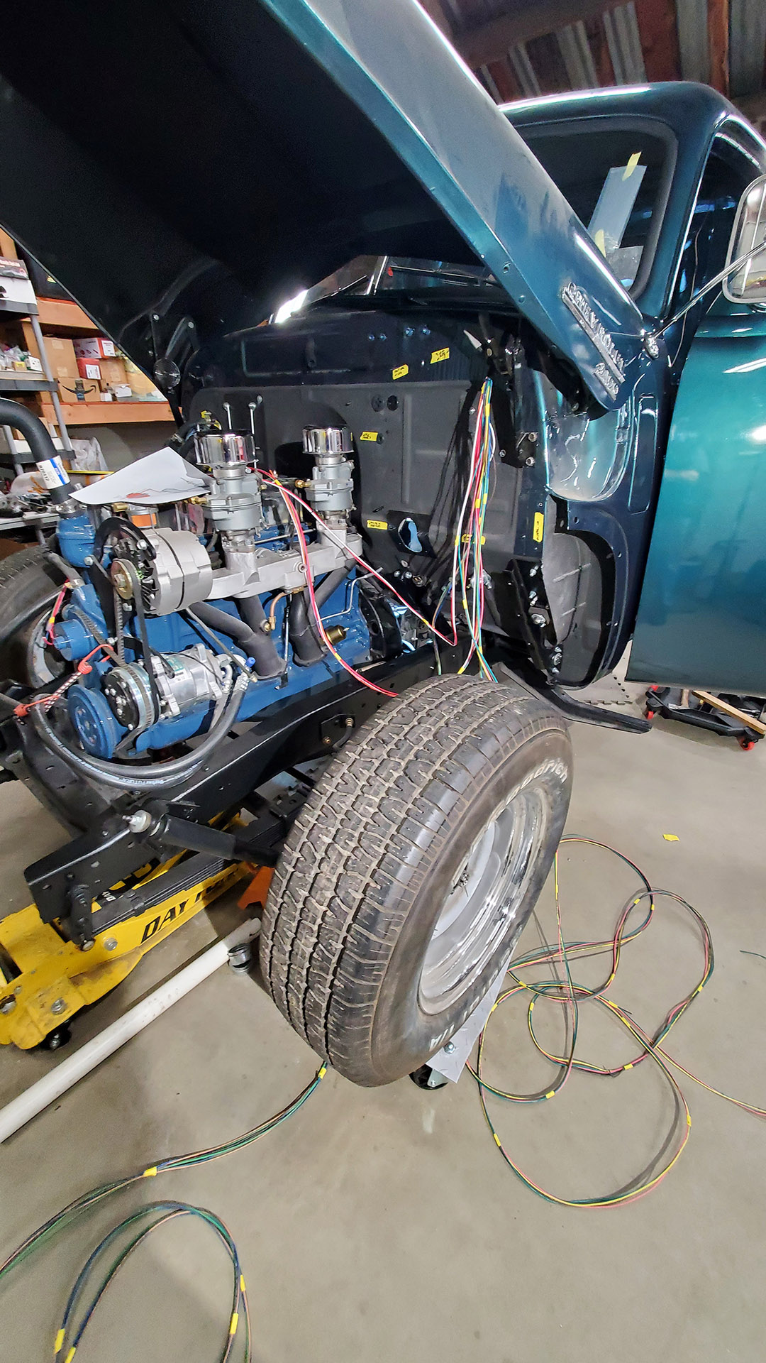
As we work along the bundle of wires we create branch circuits where wires split off to other areas or components. The first was a group of wires that travel up inside the windshield pillar and back to the rear of the cab for the dome light.
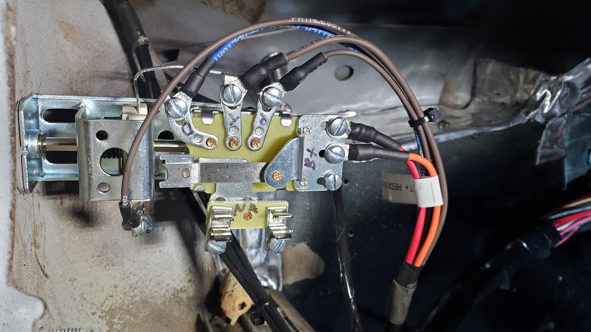
Next little branch is the headlight switch. It's an original style switch so wires get ring terminals to make the connections. We won't use all the old connection points on this switch.
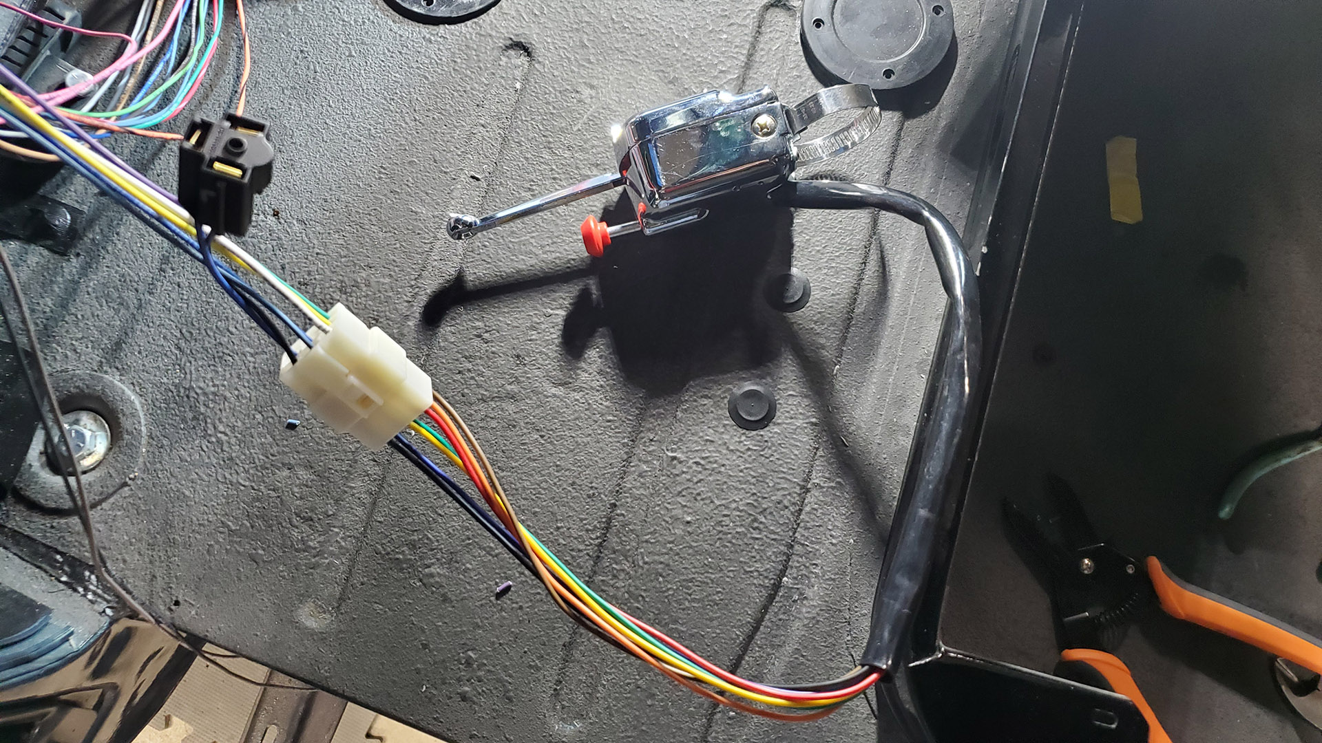
As we move across the dash, components include the instrument gauges and an aftermarket turn signal switch that someone has already added. That's right, this old truck didn't come with turn signals.
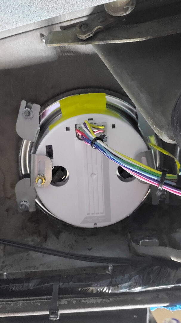
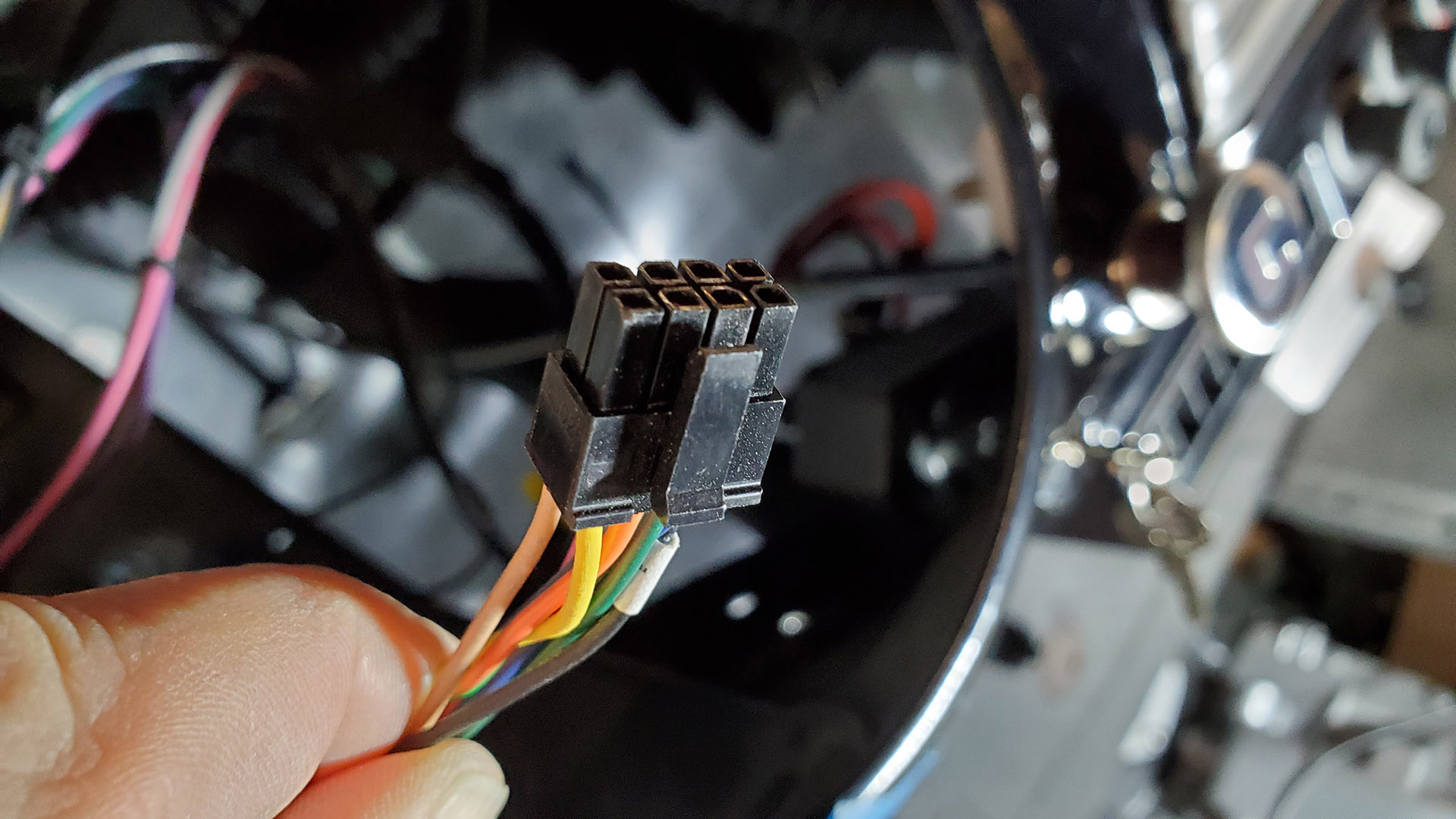
To make for a nicer installation and future servicing easier, I used multi-pin connectors or spliced provided connectors into the new harness. That way, things like the turn signal switch can actually be easily disconnected and removed. The harness literally plugs into the new speedometer and other gauge cluster.
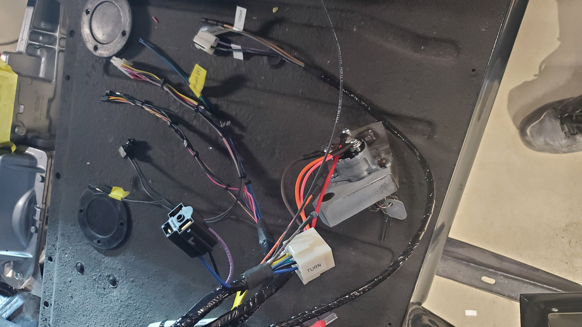
Wiring for the previously installed heat and AC system was reworked and simplified. Our new harness will plug into it.
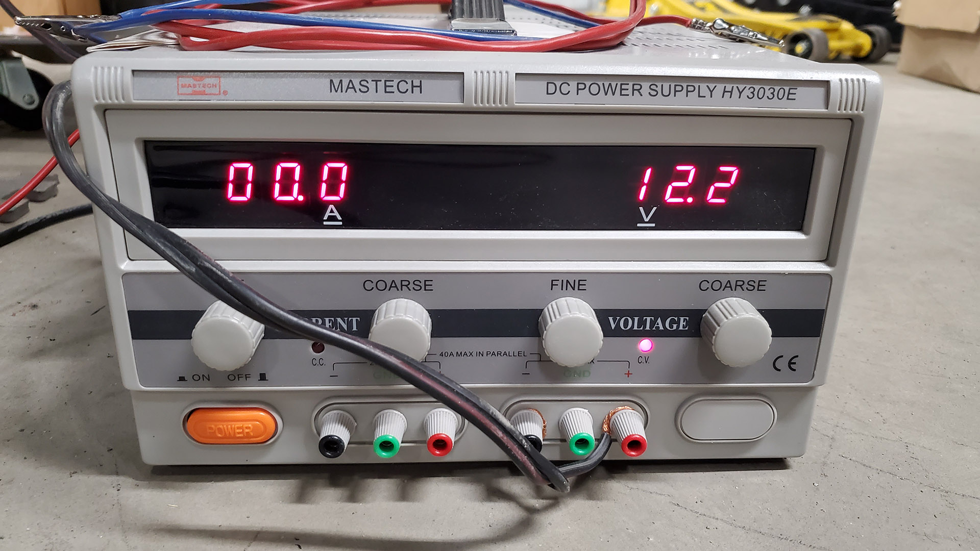
I connected a lab grade power supply to the harness so I could test circuits (like the HVAC system) as we went along.
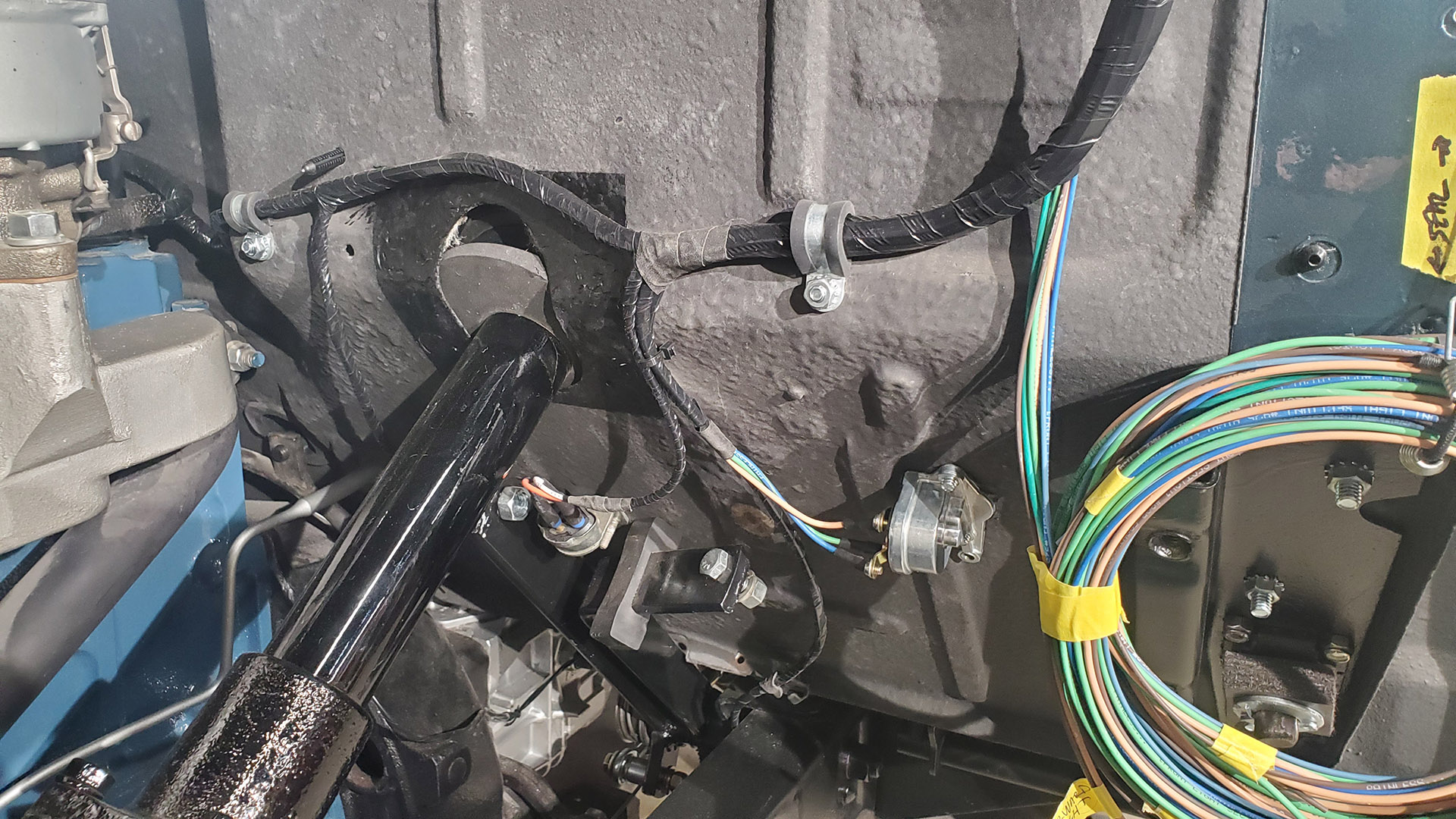
With most of the cab wiring complete, I moved to the engine side and followed a similar process of connecting branch circuits to components as we encounter them.
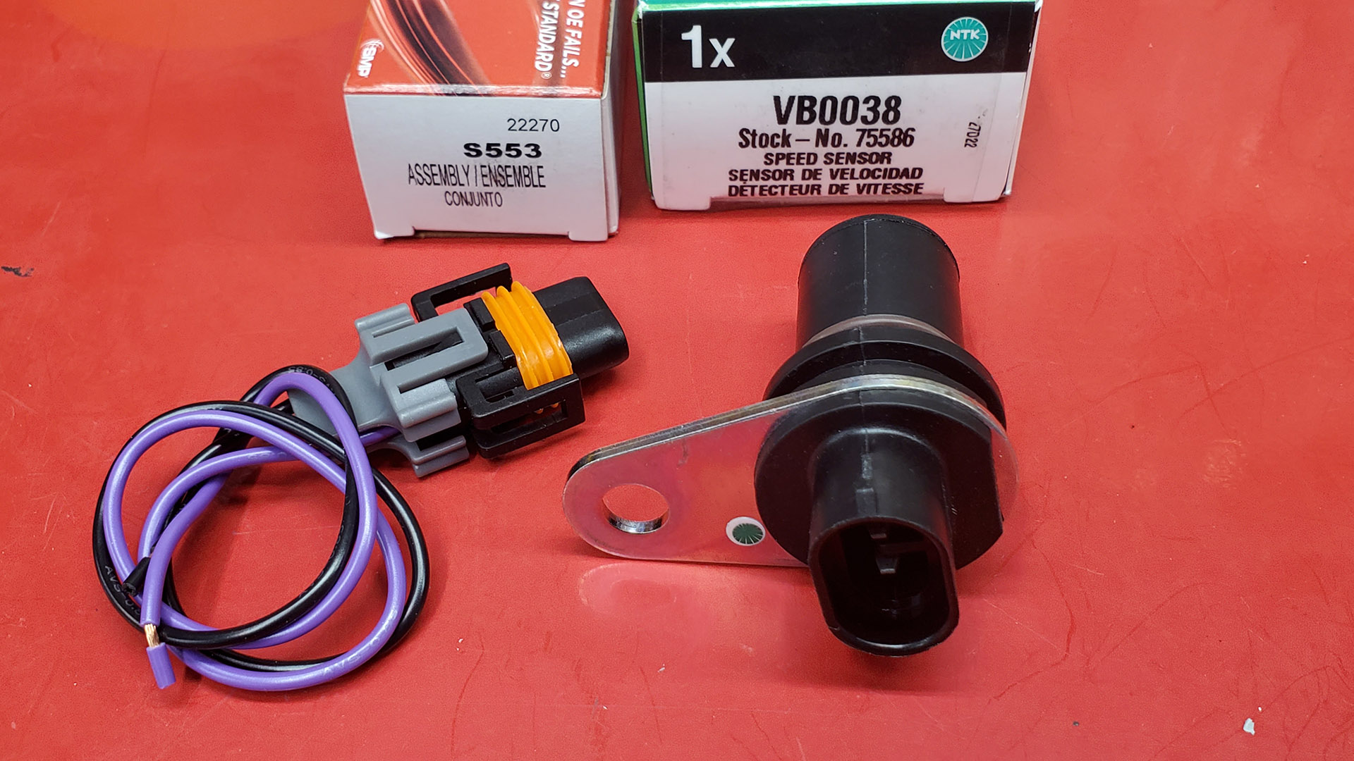
But before we forgot, a separate circuit and wires were added for the electronic speed sender in the T-5 transmission. It needs to connect to the new speedometer which will recognize such a signal.
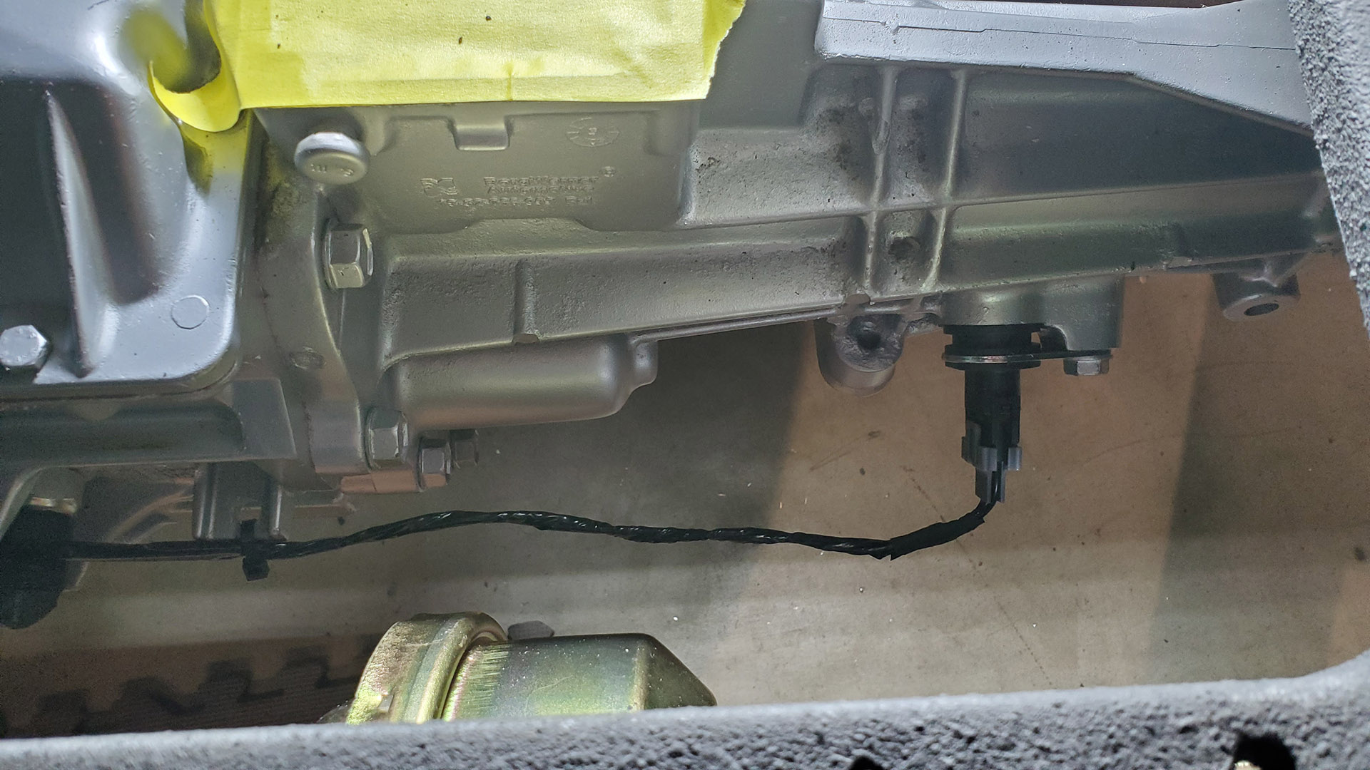
A bundle of wires was wrapped and routed along the frame rail to the rear for tail lights and the fuel tank sender.
Next in line were an original style dimmer switch that goes through the floor, a brake light switch, and oil pressure sender.
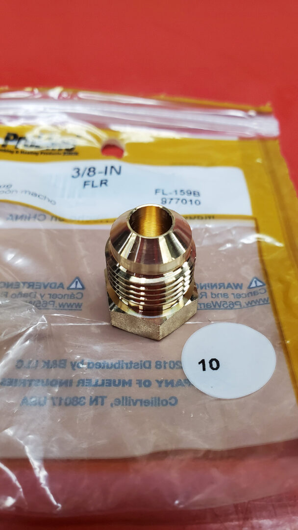
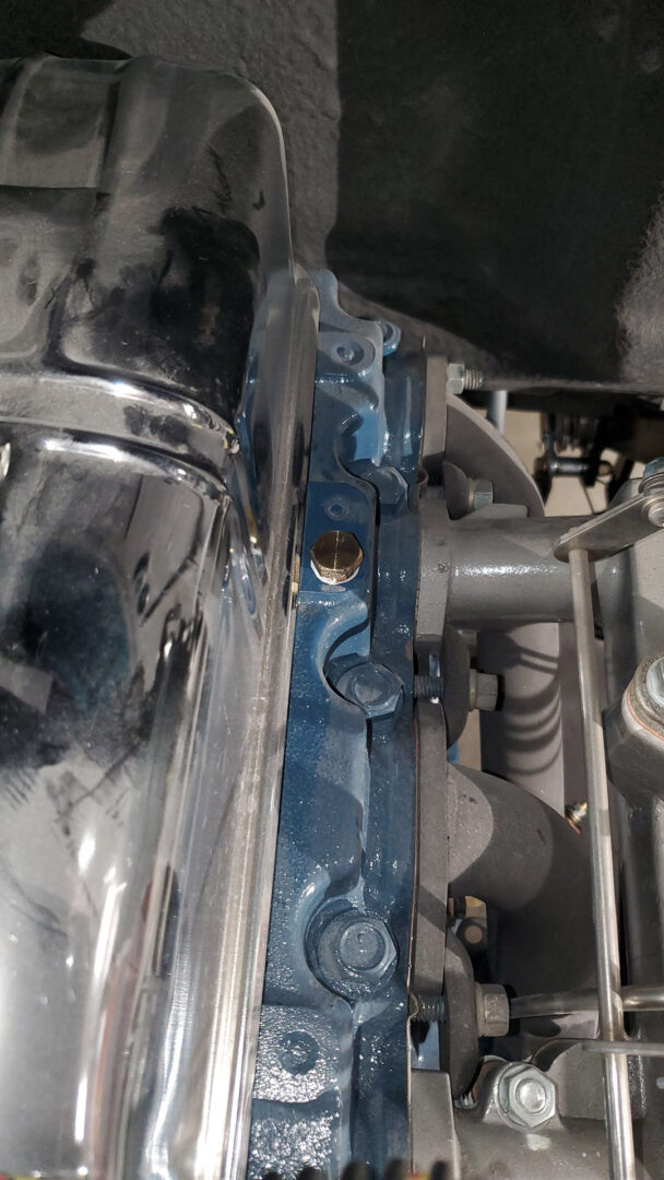
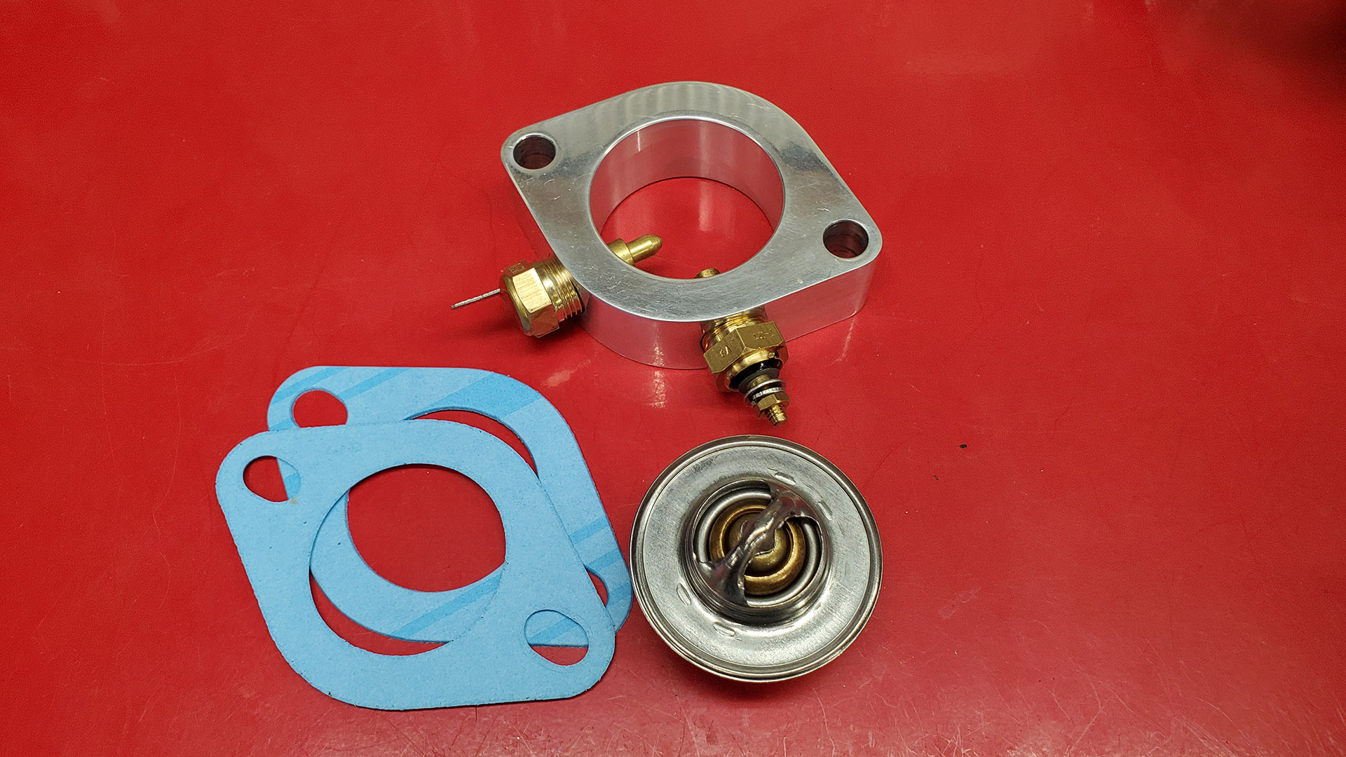
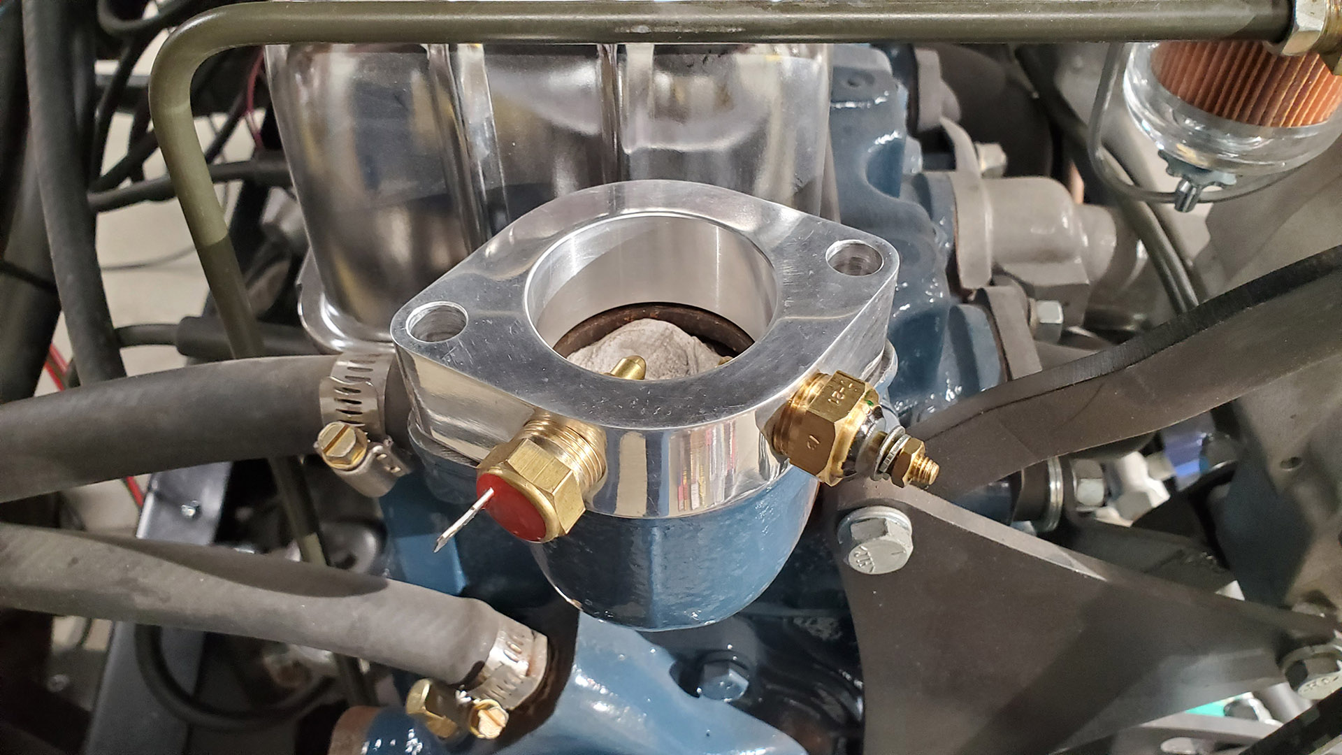
The port for the old mechanical coolant temperature sender at the back of the head was plugged and a new electrical sender was located in a spacer block at the thermostat housing.
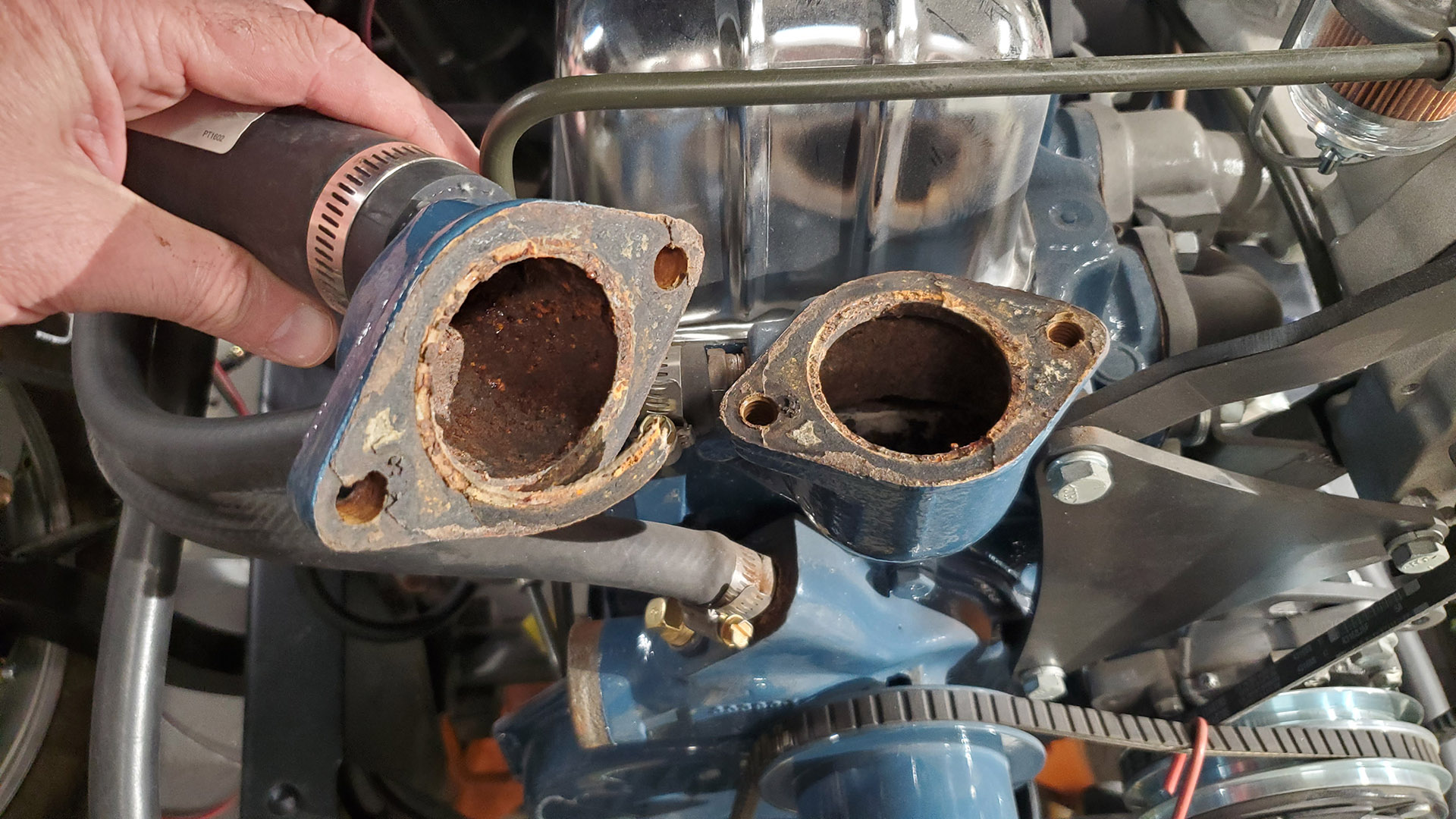
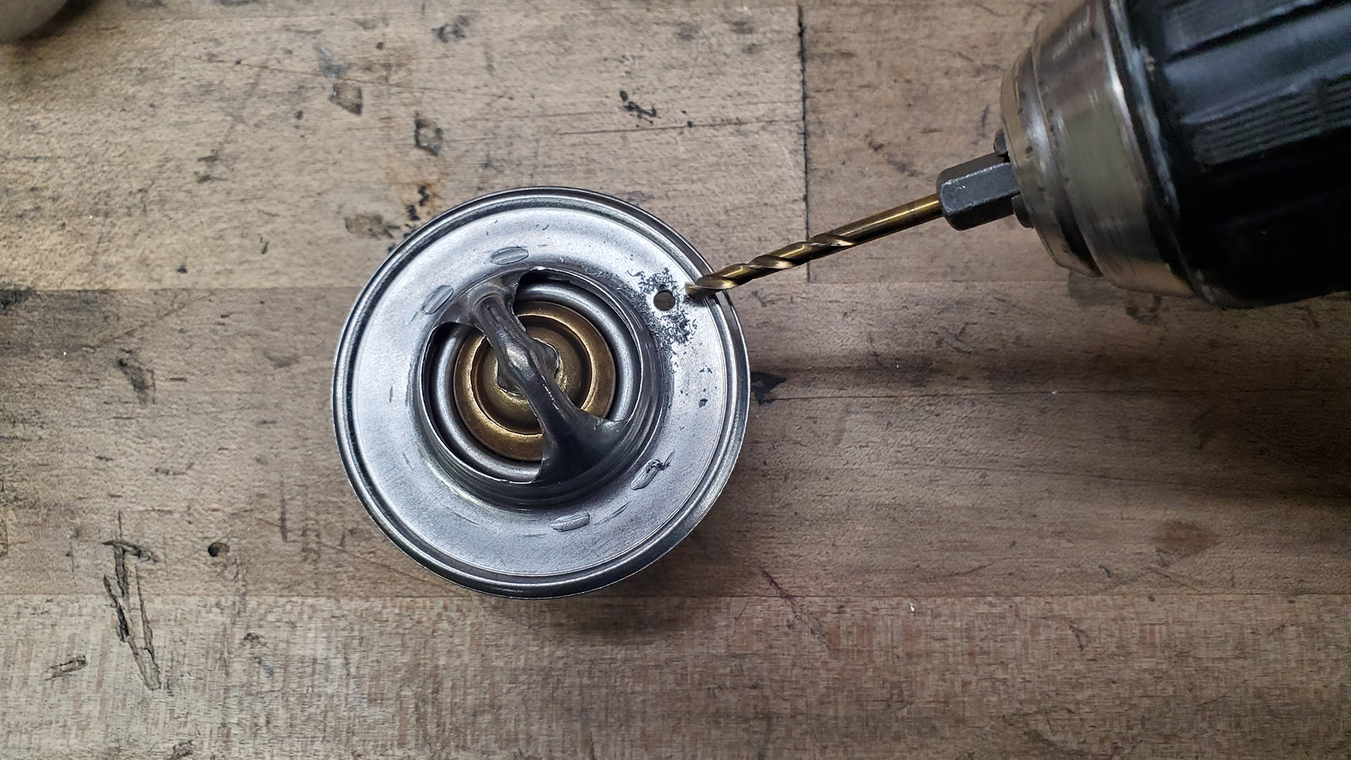
The thermostat was MIA so we installed a new one after drilling an air bleed hole. I do this on all thermostats if it doesn't have one already. This makes bleeding trapped air out of the system easier.
A branch of the harness is routed along the head and valve cover to the alternator. It includes regulator exciter wires, the charge wire that goes straight from the output of the alternator to the battery, and a wire for the new temp sender.
I repurposed some of the old style wire loom in places to add some extra heat protection. Crimped and soldered terminals with heat shrink make for tidy and reliable connections.
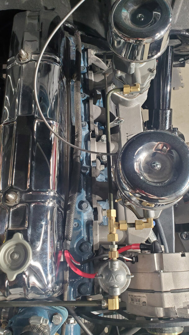
The main harness continues around the back of the head and valve cover where it it finally branches to the ignition coil and down to the battery which is stowed under the cab floor.
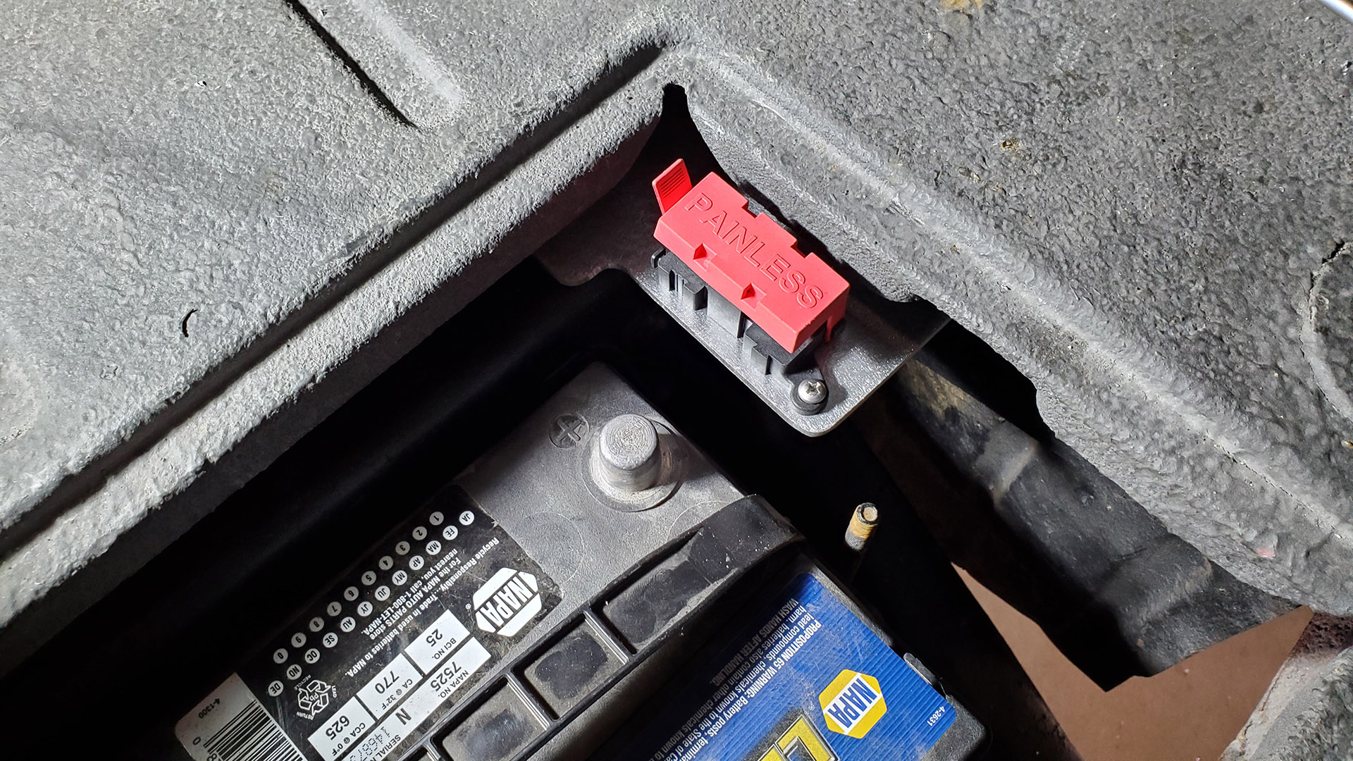
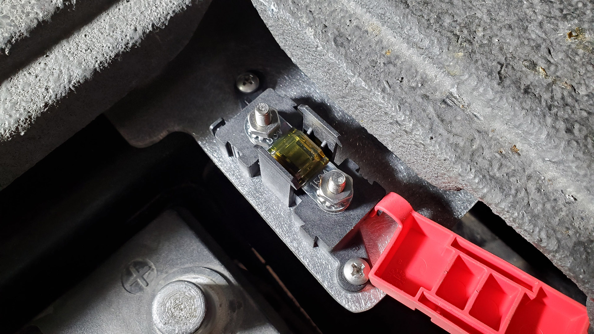
Here, I fabbed a small bracket to mount the main protective fuse for the entire system. Rather than use a fusible link, Painless supplies a 150 amp Midi fuse. The goal is to get system protection as close to the battery as possible.
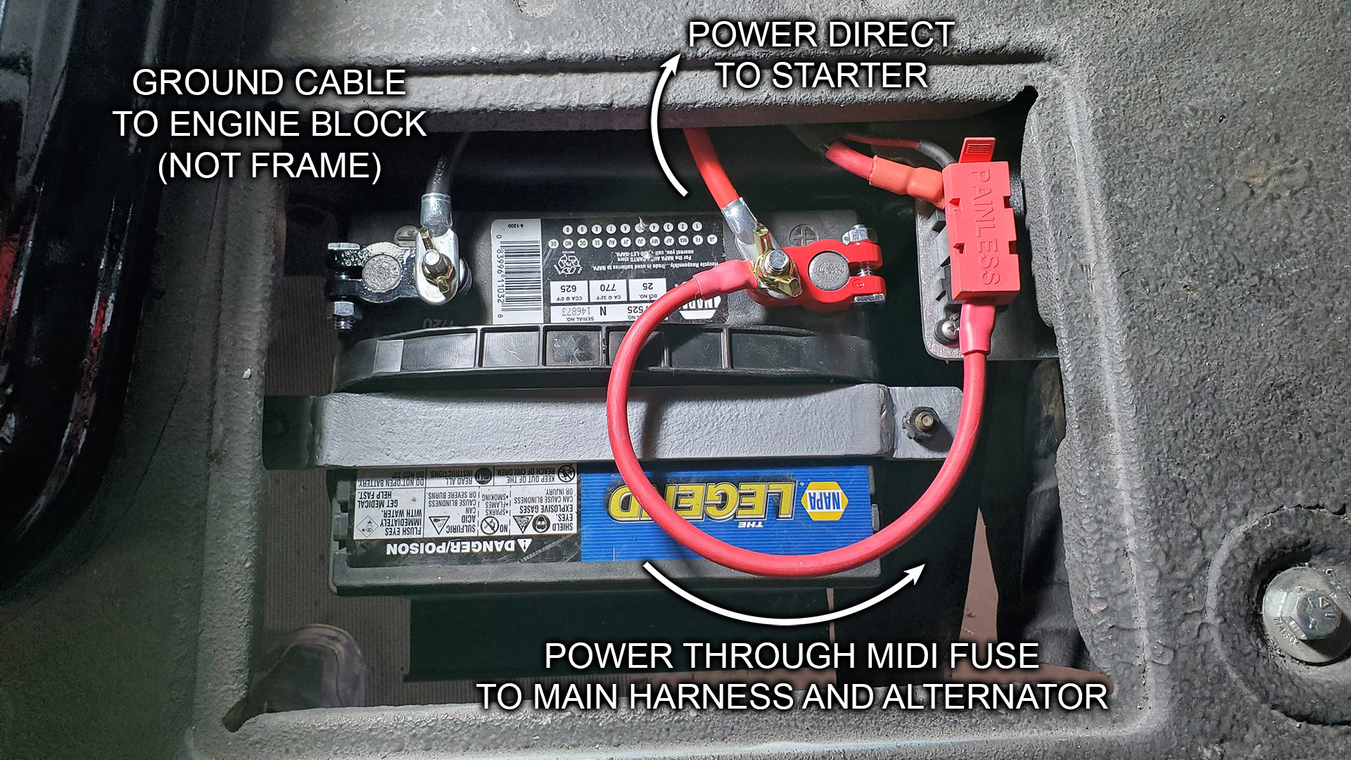
It looks a little strange but here are the final connections at the battery. I used Marine style terminals so that cables can be easily connected. I also didn't want to stack several connections at the starter motor post.
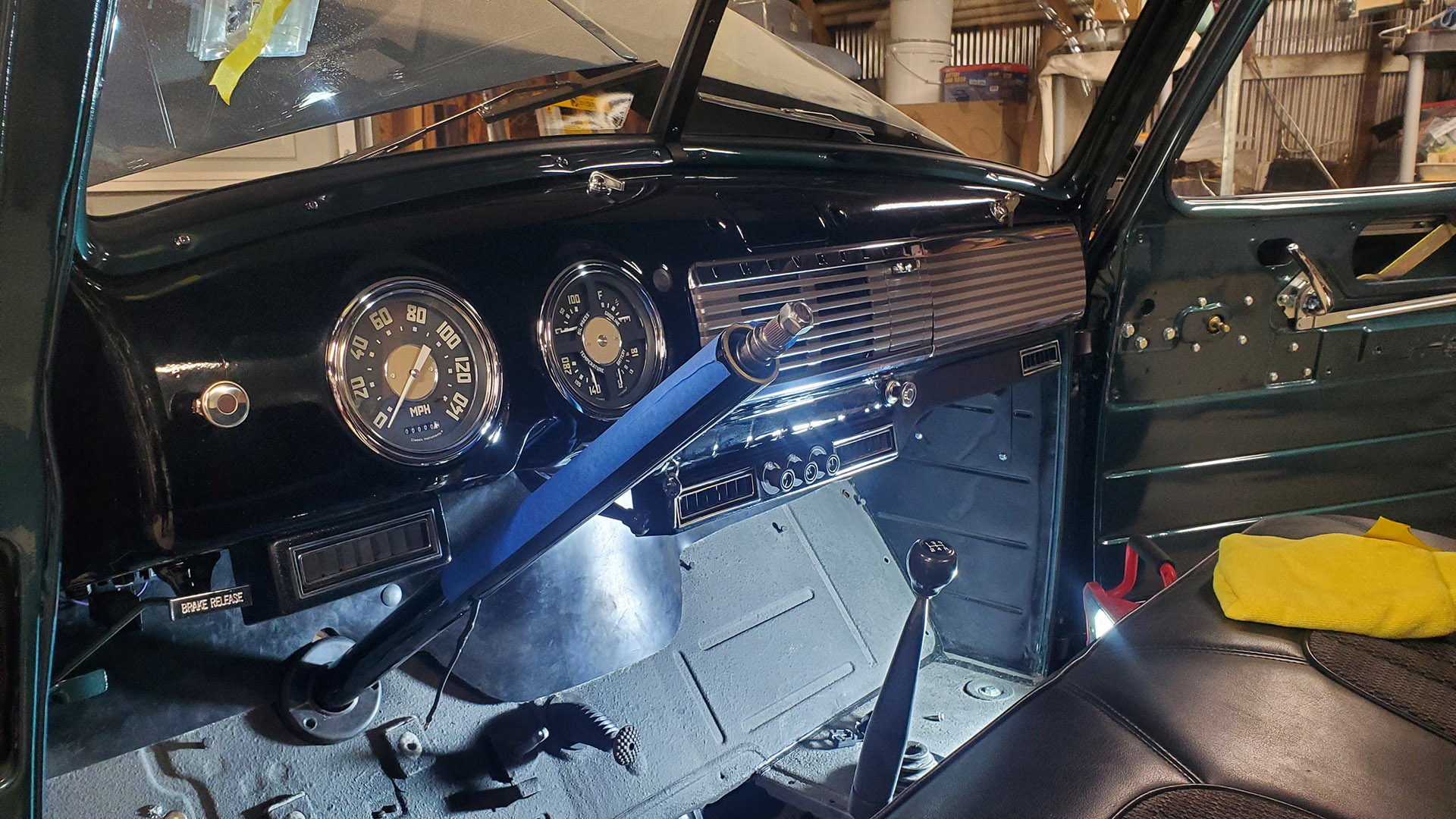
Meanwhile, back inside the cab, I get more of the dash assembled (speakers, grille, and gauges, cigar lighter, and glove box door).
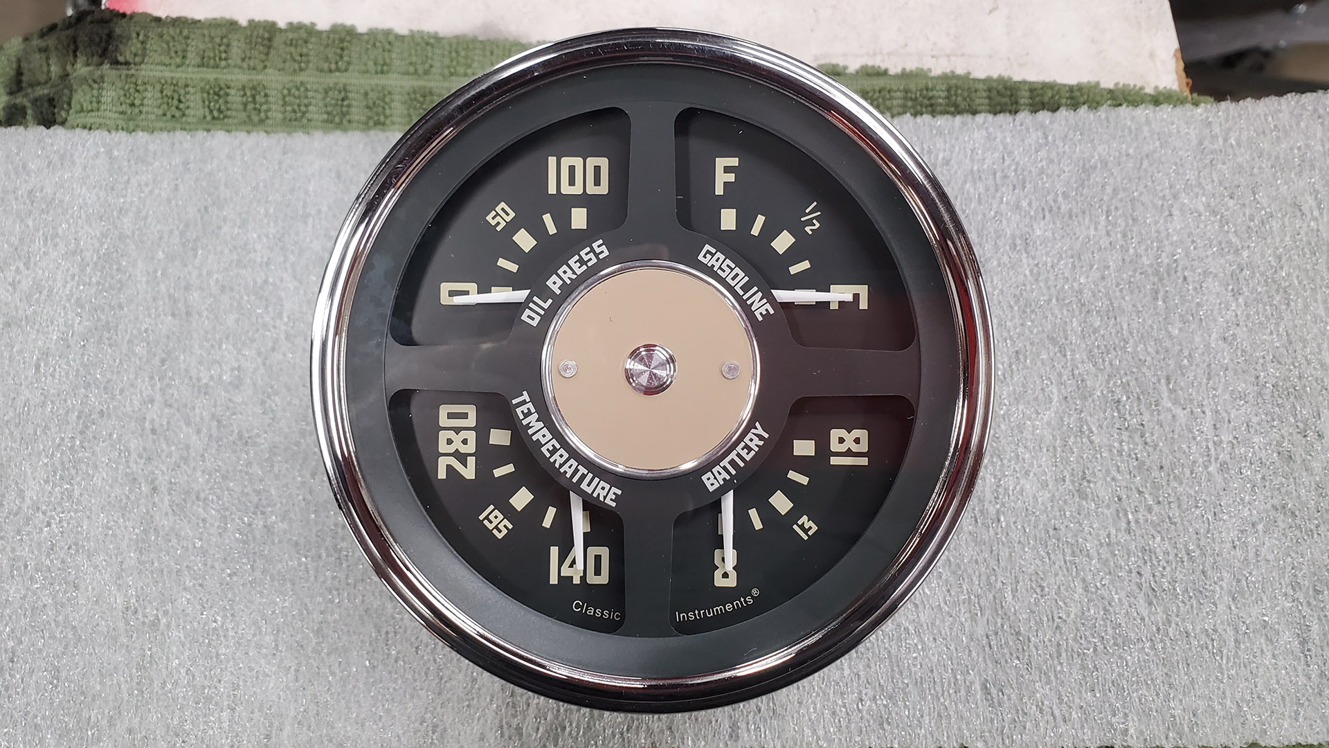
Let's take a closer look at the instruments and why we switched to these rather than use the old ones.
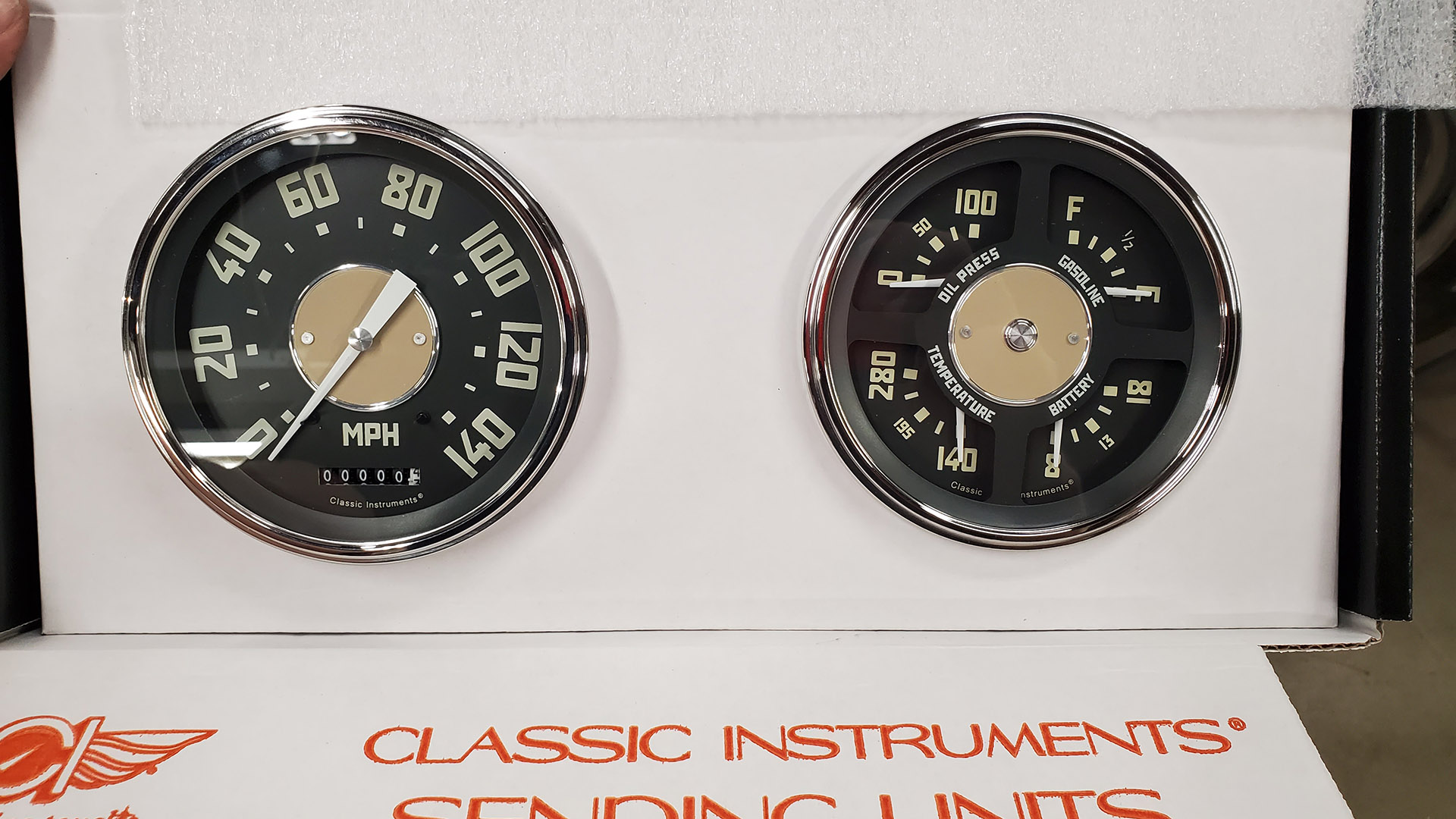
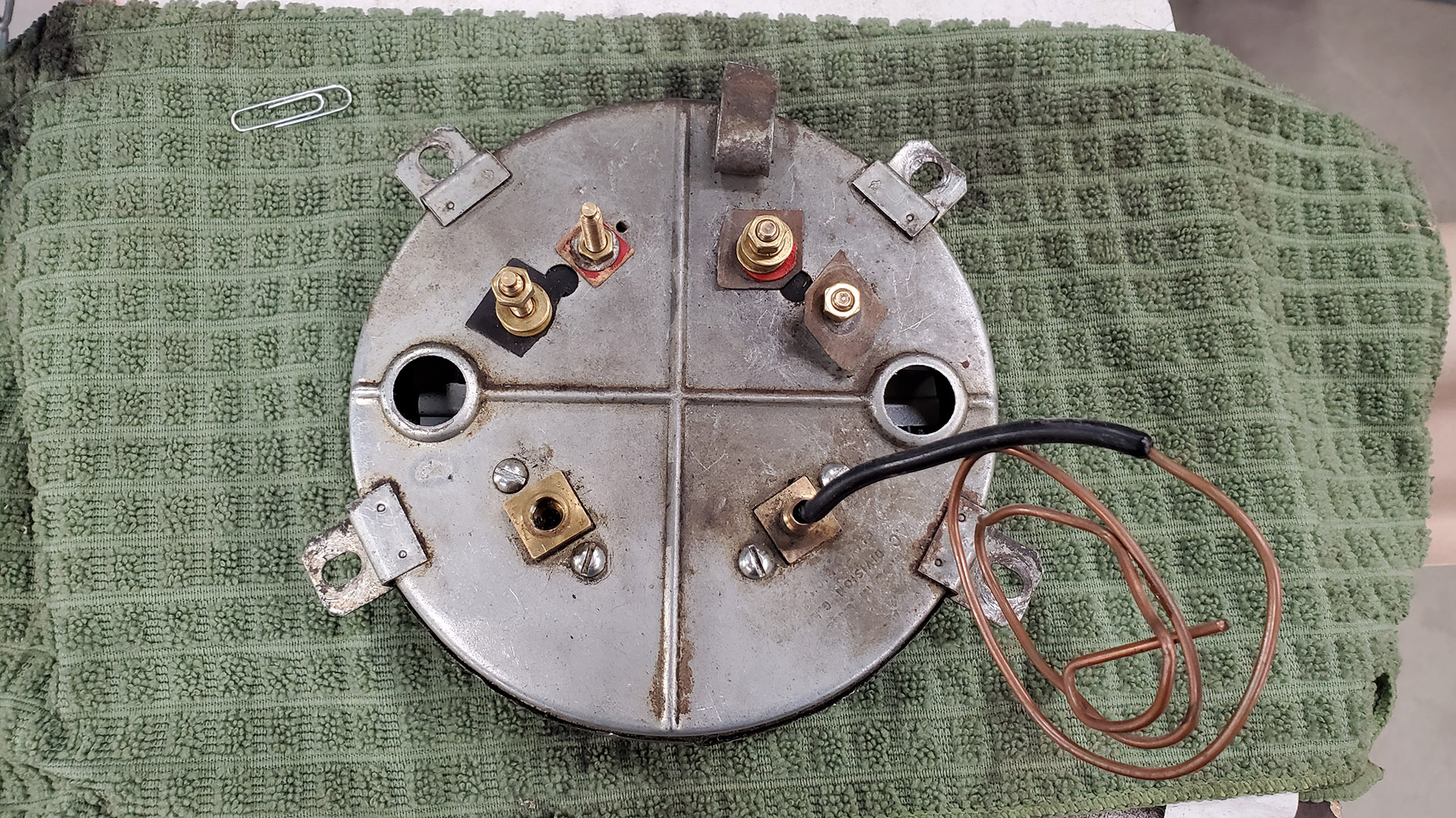
The speedo had already been replaced at least once. The problem is, it's mechanically driven with a cable from the transmission. Our 'new' T-5 transmission uses an electronic speed sender. There's no way to join the two without major changes or expensive adaptations.
The new electric speedo will accept the a signal from the T-5 and is programmable to calibrate it. I setup the harness to just plug into it.
Take a close look at this next picture of the original gauge cluster. Can you spot what's wrong with one of the gauges?
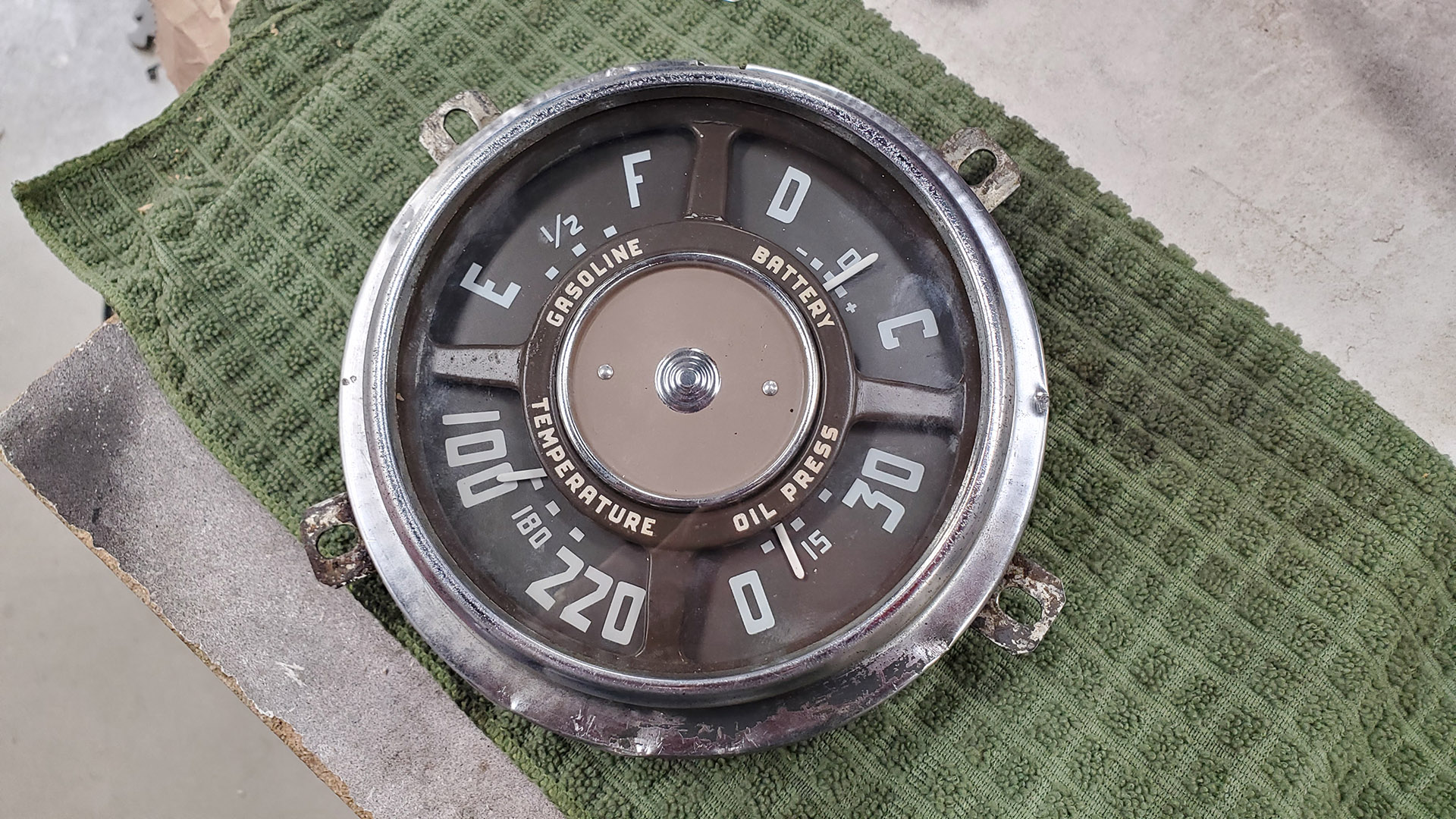
The fuel gauge is fried and has no pointer. The one marked 'Battery' is actually an AMP gauge. Normally the main power feed runs through this and it's supposed to give the driver an idea of the state of the charging system (discharging or charging) but it doesn't mean much to most people these days. It has largely been replaced by a voltage gauge - which is different.
The temperature gauge and oil pressure gauges are mechanical (which is fine) but these are useless because the capillary tube has been severed on one and the hard line is gone to the other and is not reading zero at rest. If the line fails inside the cab you lose oil pressure to the engine and your feet get a bath in hot oil.
Modern internals. Remote electric sending units. Voltage gauge. Looks old-school like the original. Plug it in.
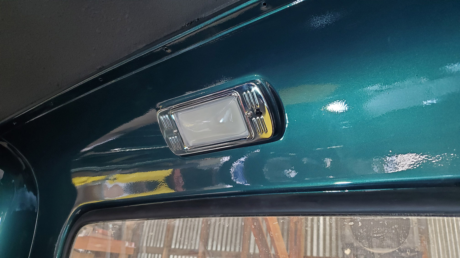
A new dome light fixture replaces the old one which was messed up.
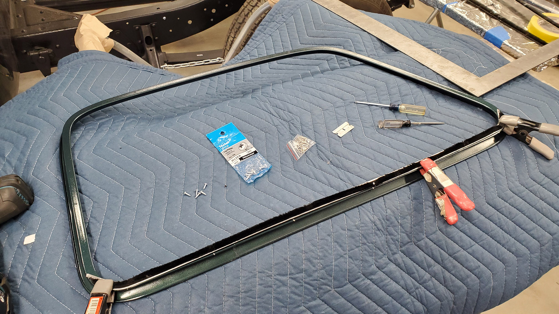
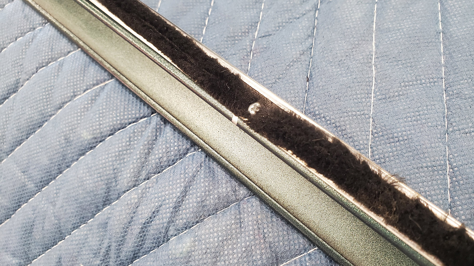
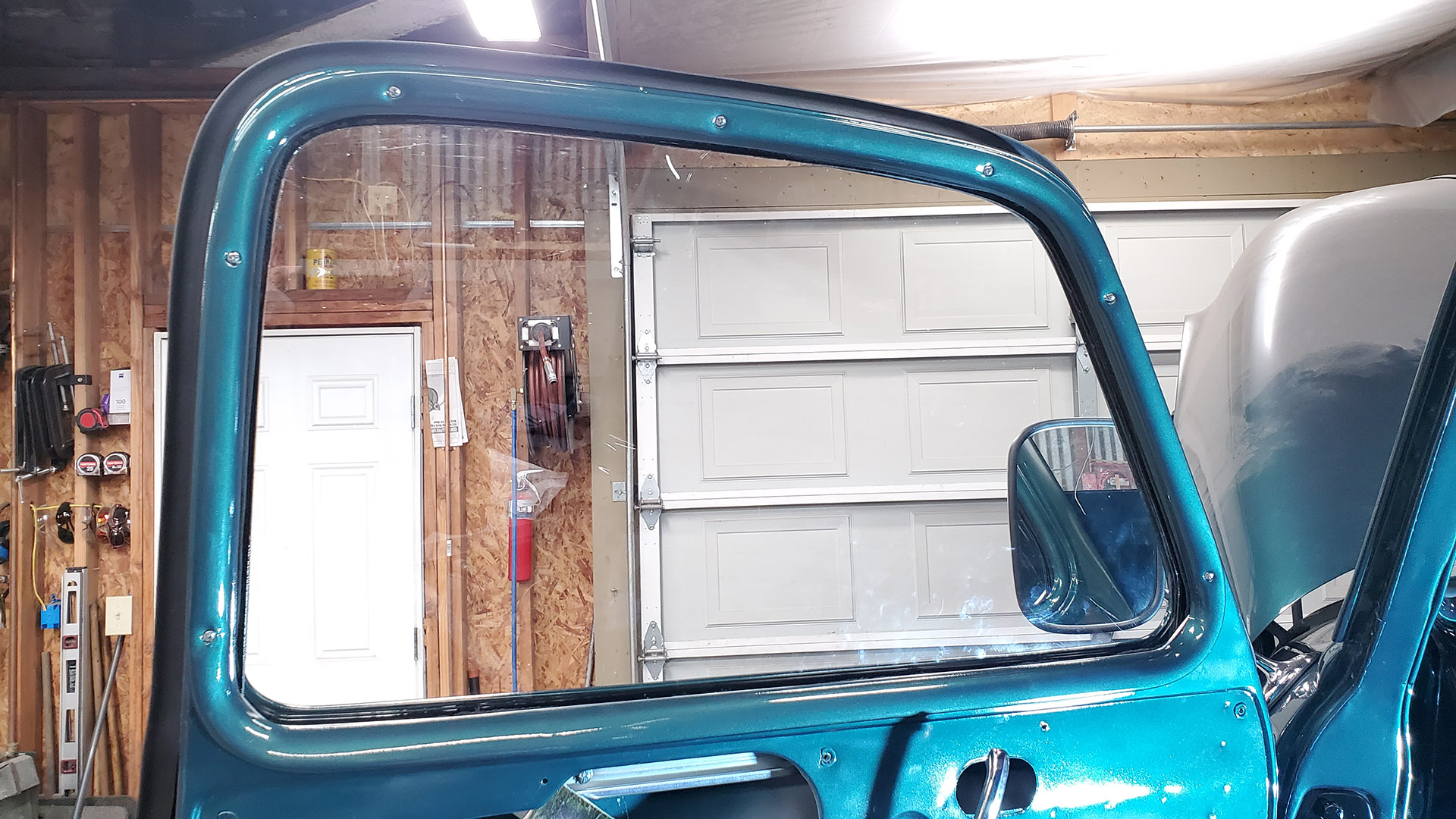
On other fronts, I installed the window sweeps (inner fuzzy) to our freshly painted side window garnish mouldings. The originals were actually stapled to the mouldings. That had to be one heavy duty stapler! More practically, these can be pop riveted in place (which I've done before) or, in this case, I used tiny #4 screws. The heads get buried in the fuzz.
In our next installment we'll cover more of the interior. So many details, bits, and pieces!
