Progress on the ’50 Chevy Pickup
After a couple of delays and setbacks we're making (frustratingly) slow but steady progress on the '50 Chevy pickup. At this point it feels like we've mostly crested the hump of undoing and redoing old work and can begin to move forward with the actual task of assembling the truck. There will be some inevitable delays. Any time something has to be ordered, it can take a week to arrive. There are some pieces that still have to be painted with automotive finishes and that's a process all on its own. The nice thing is we've stockpiled a lot of parts for the dash and cab.
As we look at the overall progress it doesn't seem that significant until you consider all the small details that go into each larger system. In our last post we left off with installation of the transmission and clutch. We then jumped back on the rear axle to get it finished up.
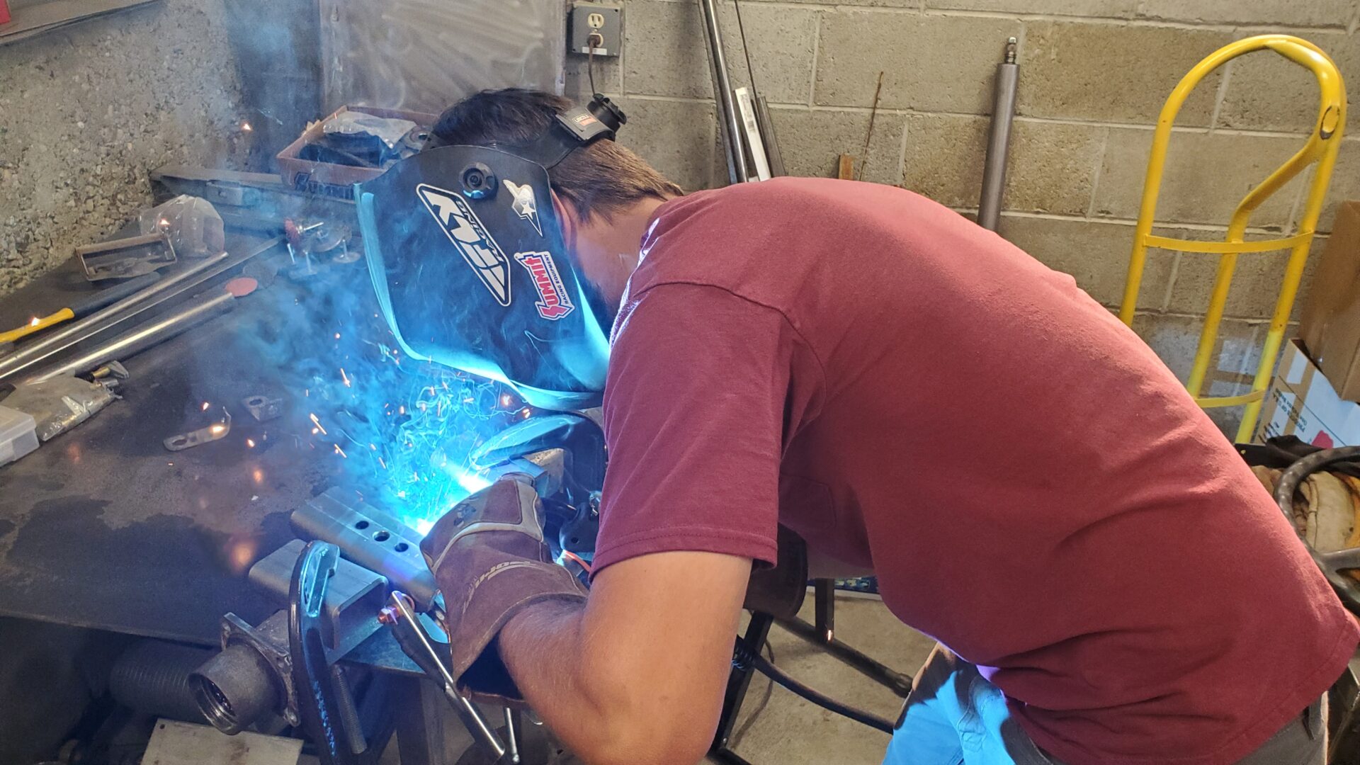
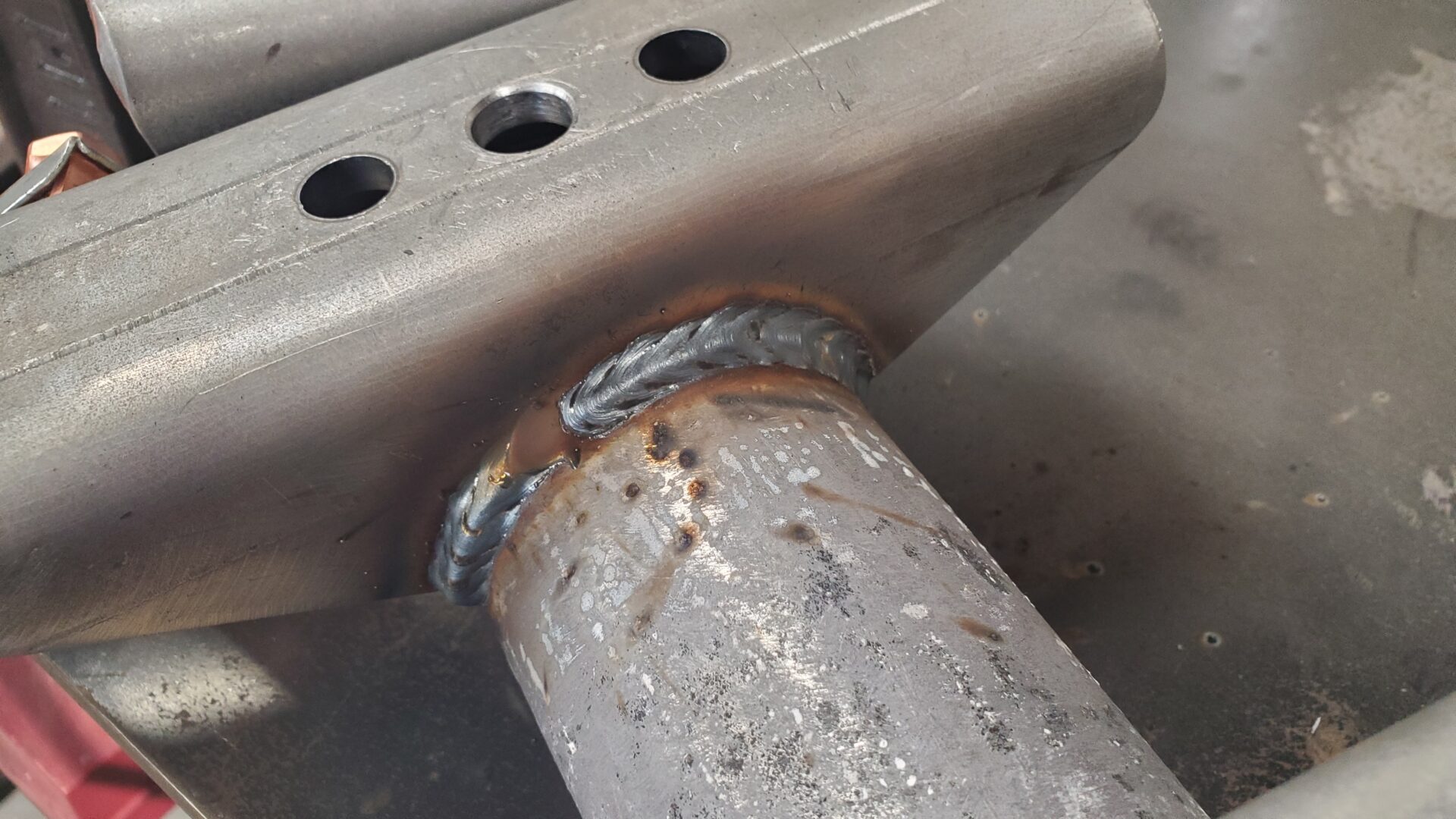
Originally, the hope was to be able to just clean up the axle, install some new seals, and run it. But, alas, it has seen a lot of miles, or abuse, or both. There were obvious signs someone had been inside. Tolerances were off. It was loosey-goosey where it shouldn't be. Still, this is a way better option than the axle the truck came in with.
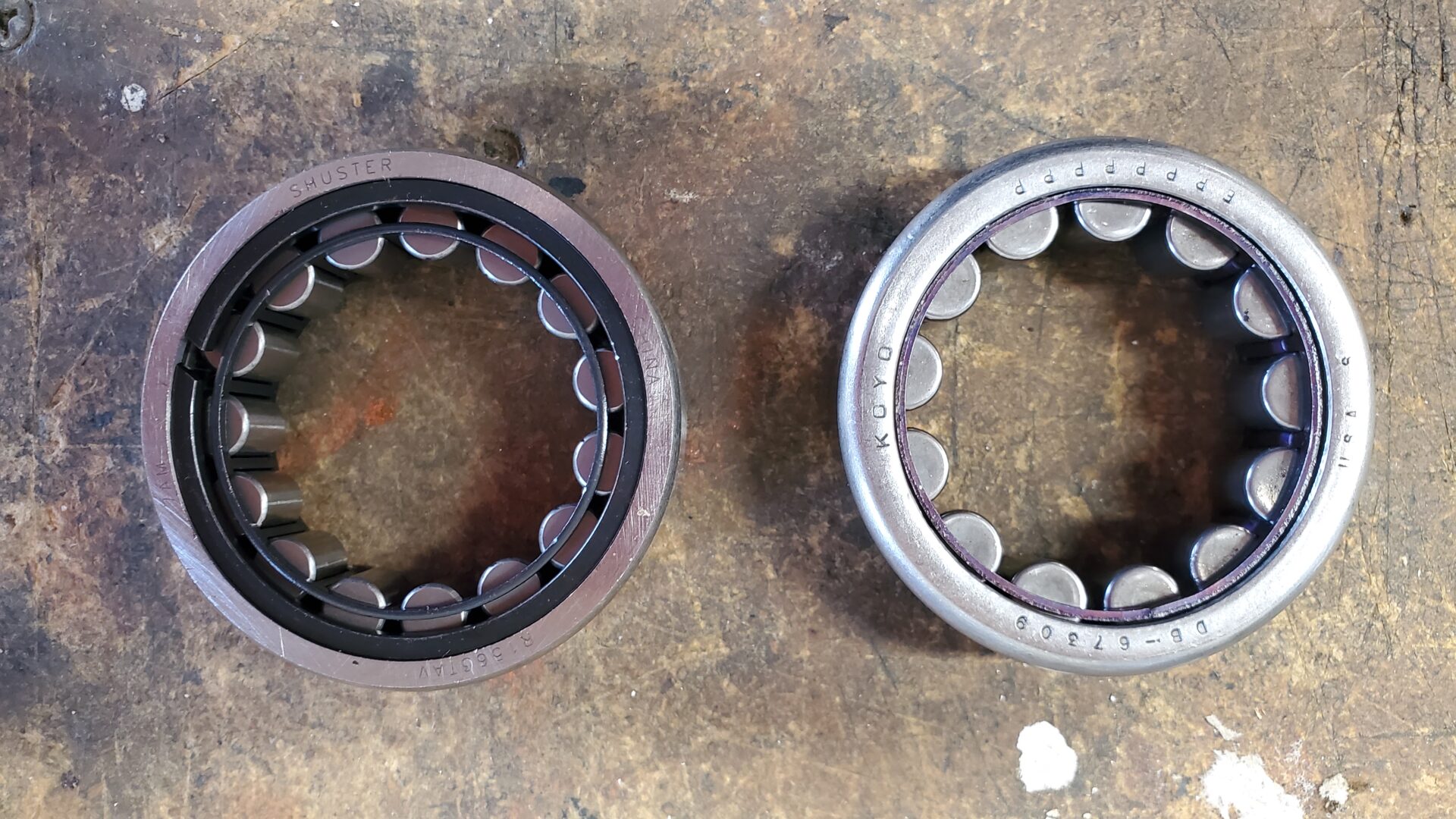
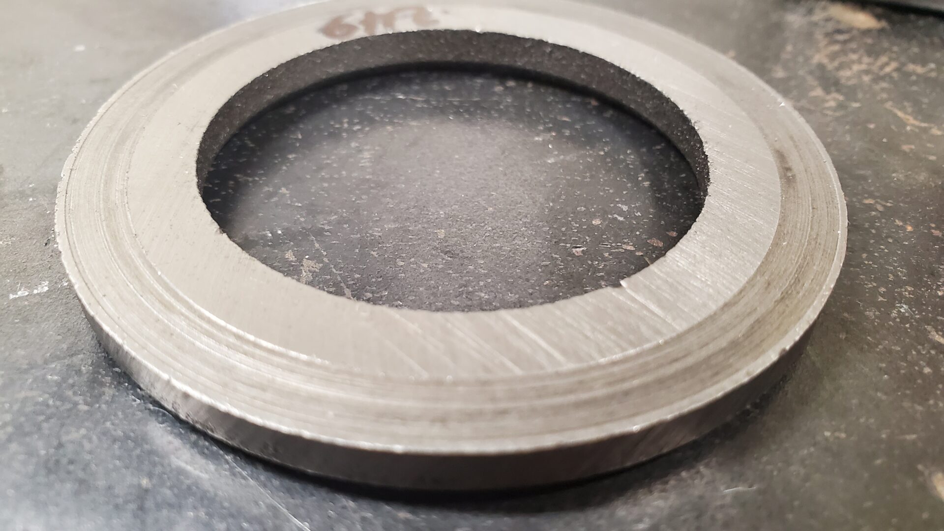
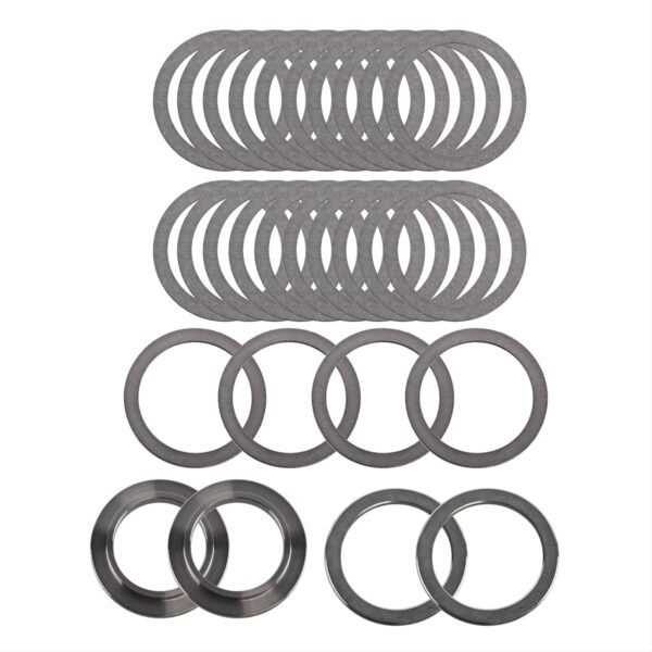
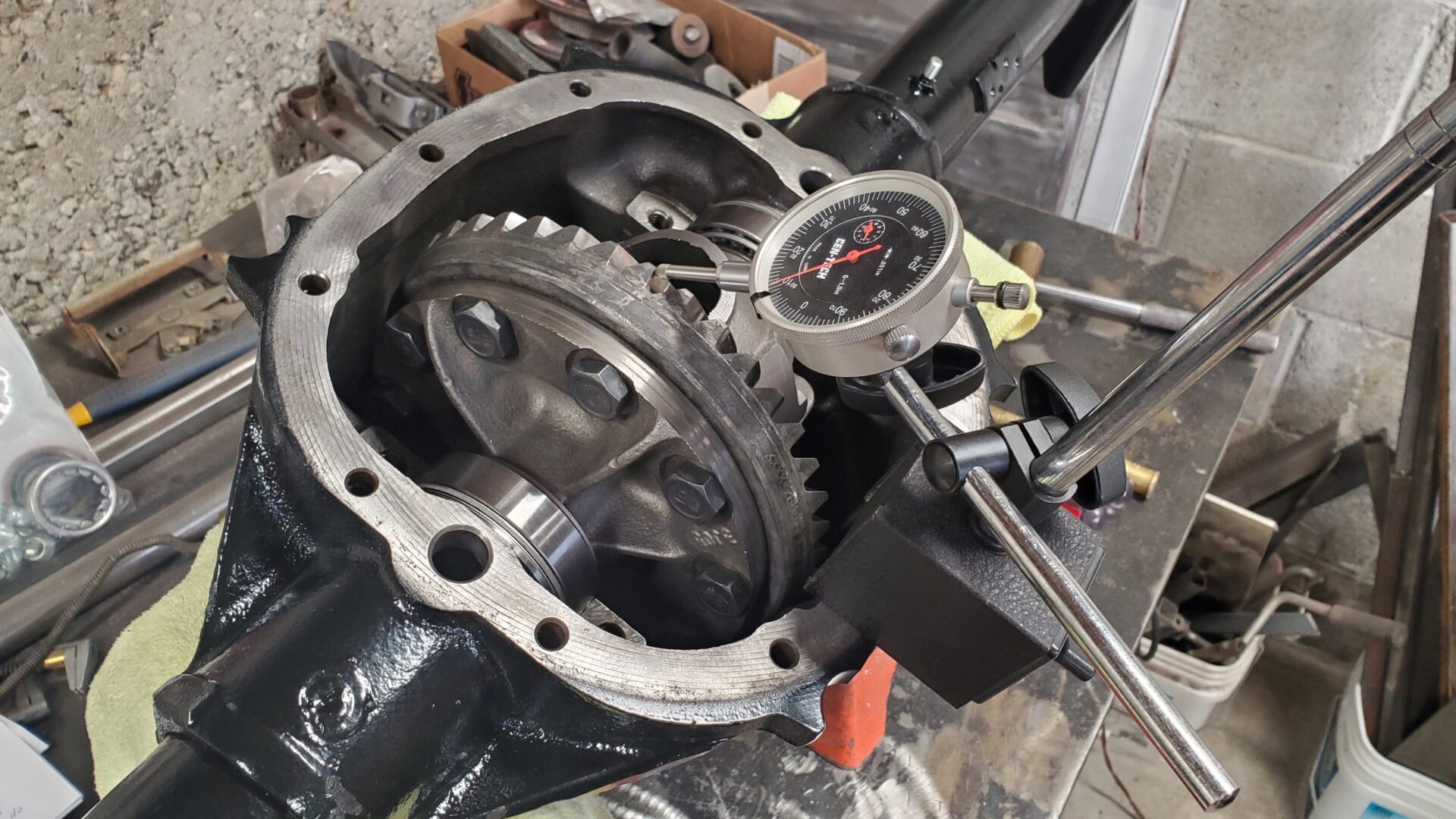
We put in some new bearings and seals but stopped short of a ring and pinion. (A bad choice, perhaps. We'll see). The pinion gets a new crush sleeve. The ring and pinion backlash and bearing preloads were reset to factory specs and we'll keep our fingers crossed that it won't howl like a banshee. Are we feeling lucky or what?
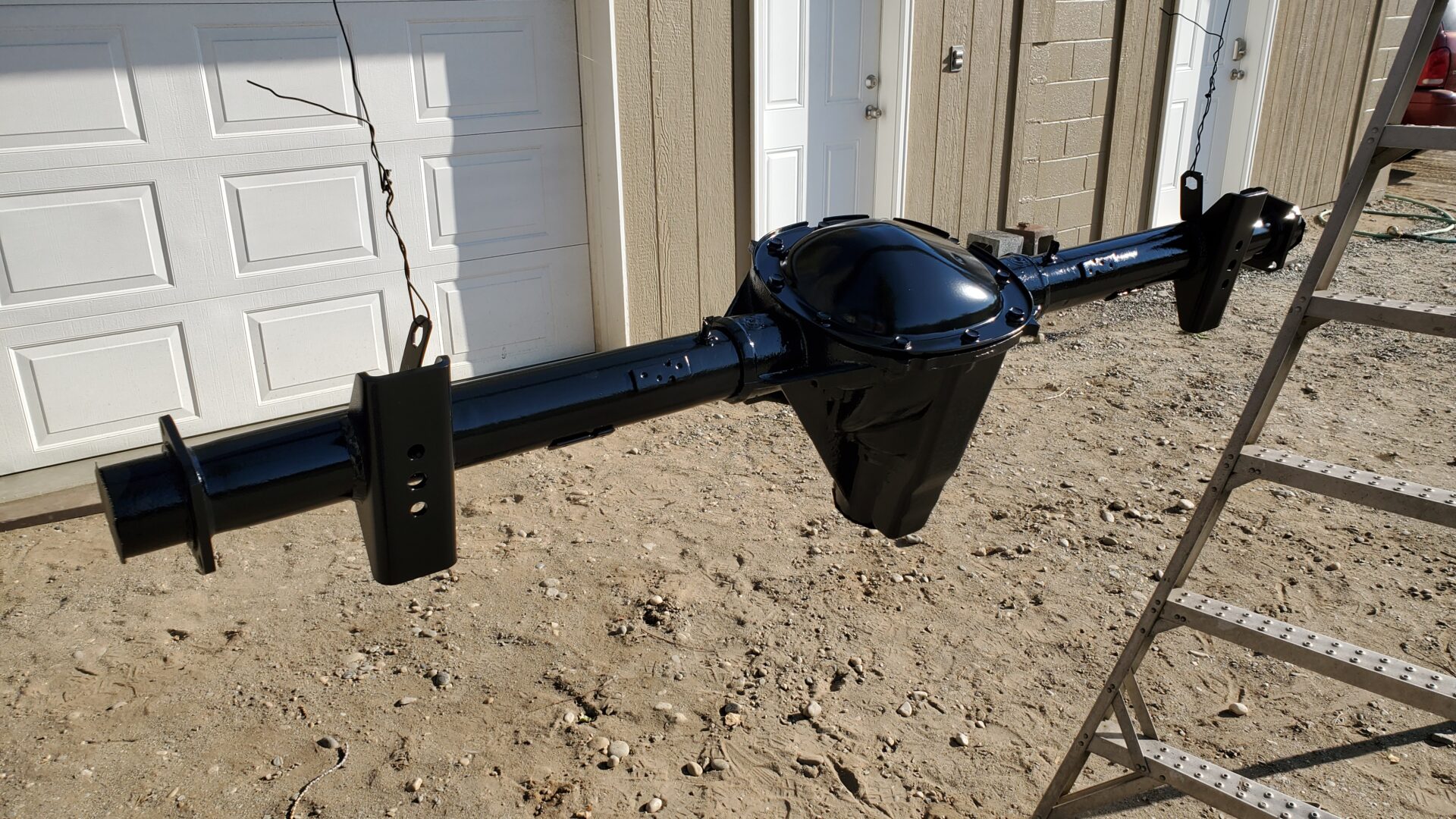
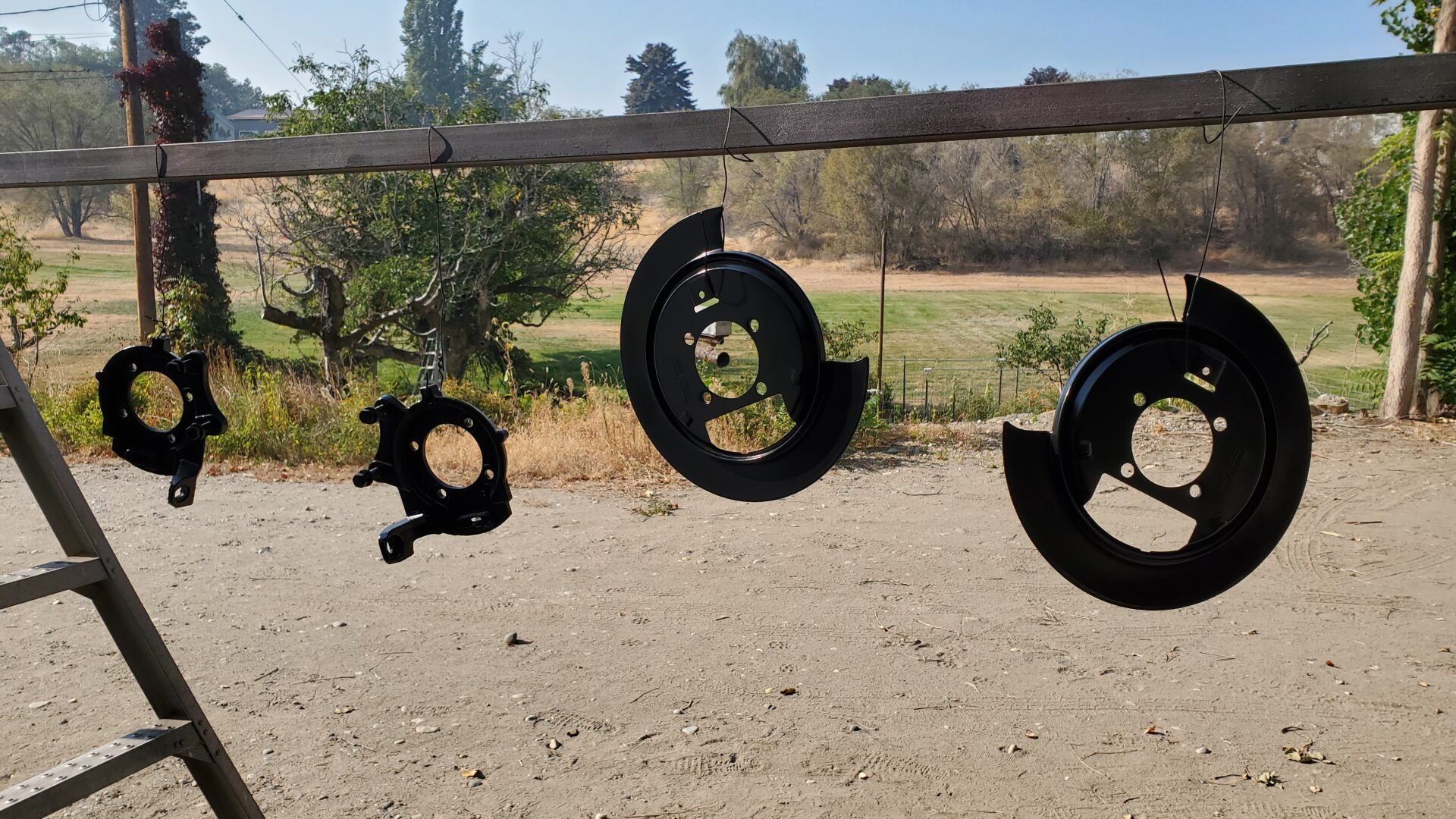
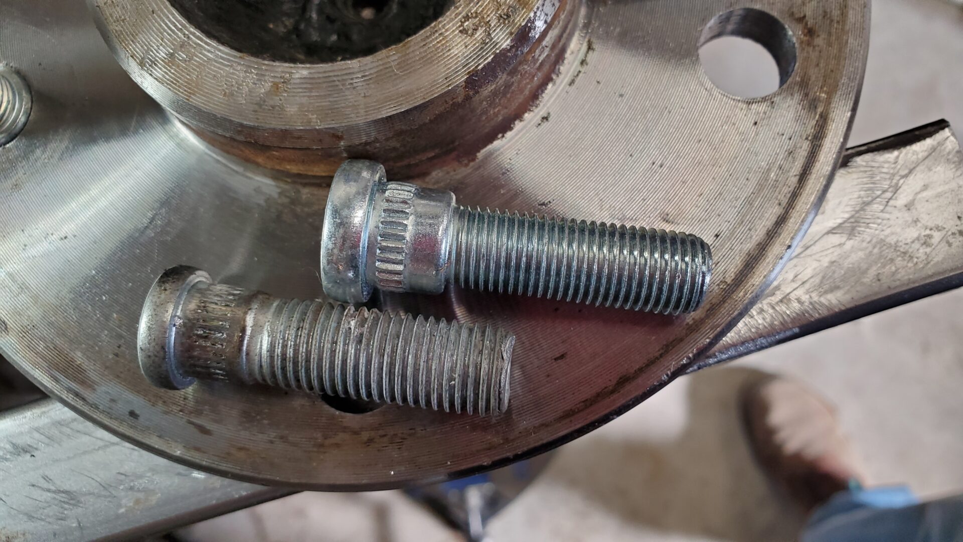
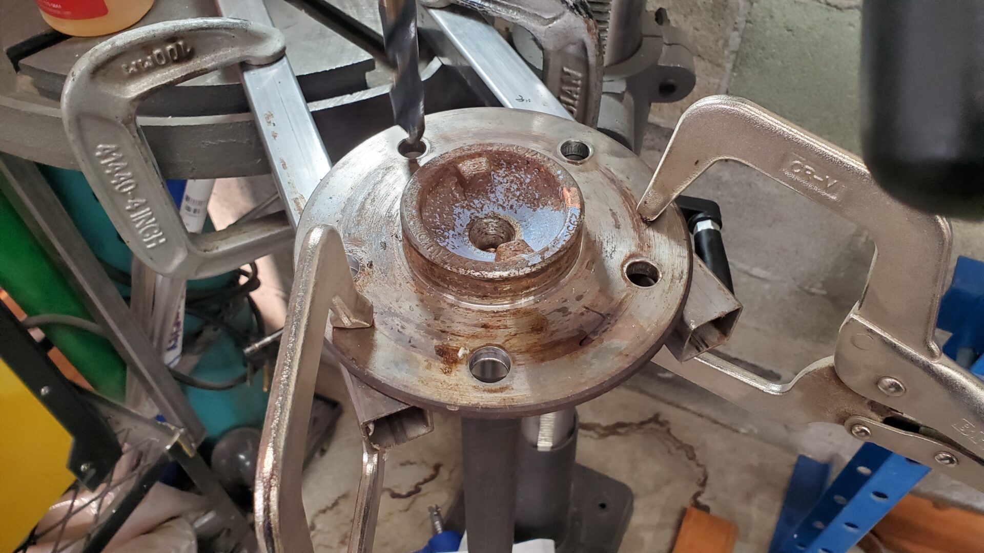
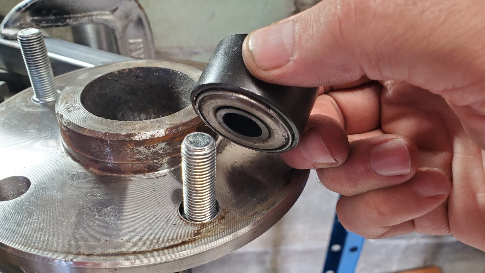
The Chevy S-10 axles have metric-sized wheel studs. In order for them to match the non-metric, 7/16" studs on the front, we knocked the old studs out, drilled out the holes to 35/64", and pressed in the correct size wheel studs. (Dorman 610-156).
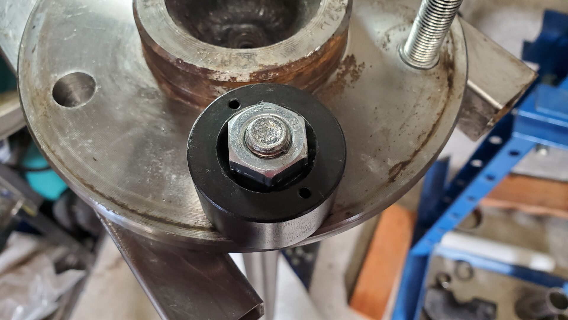
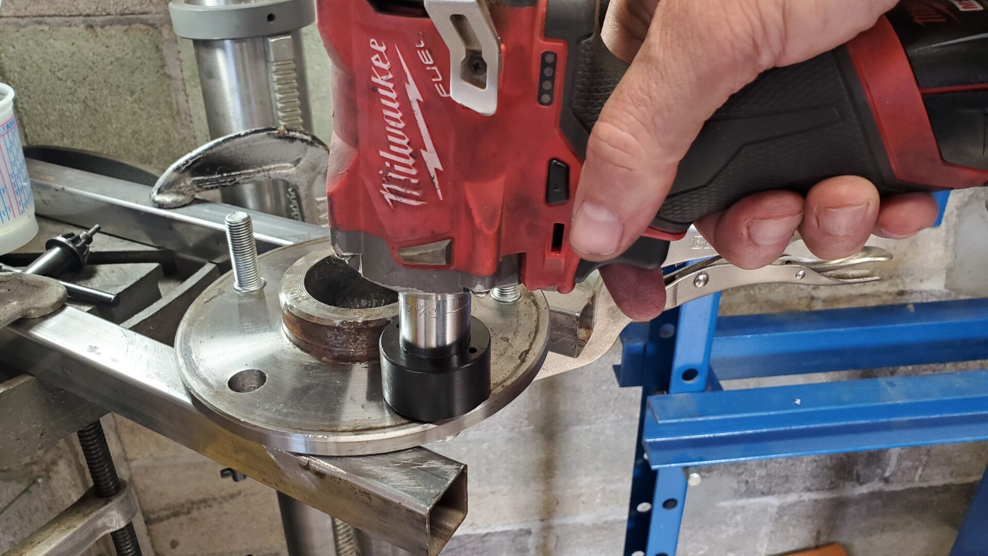
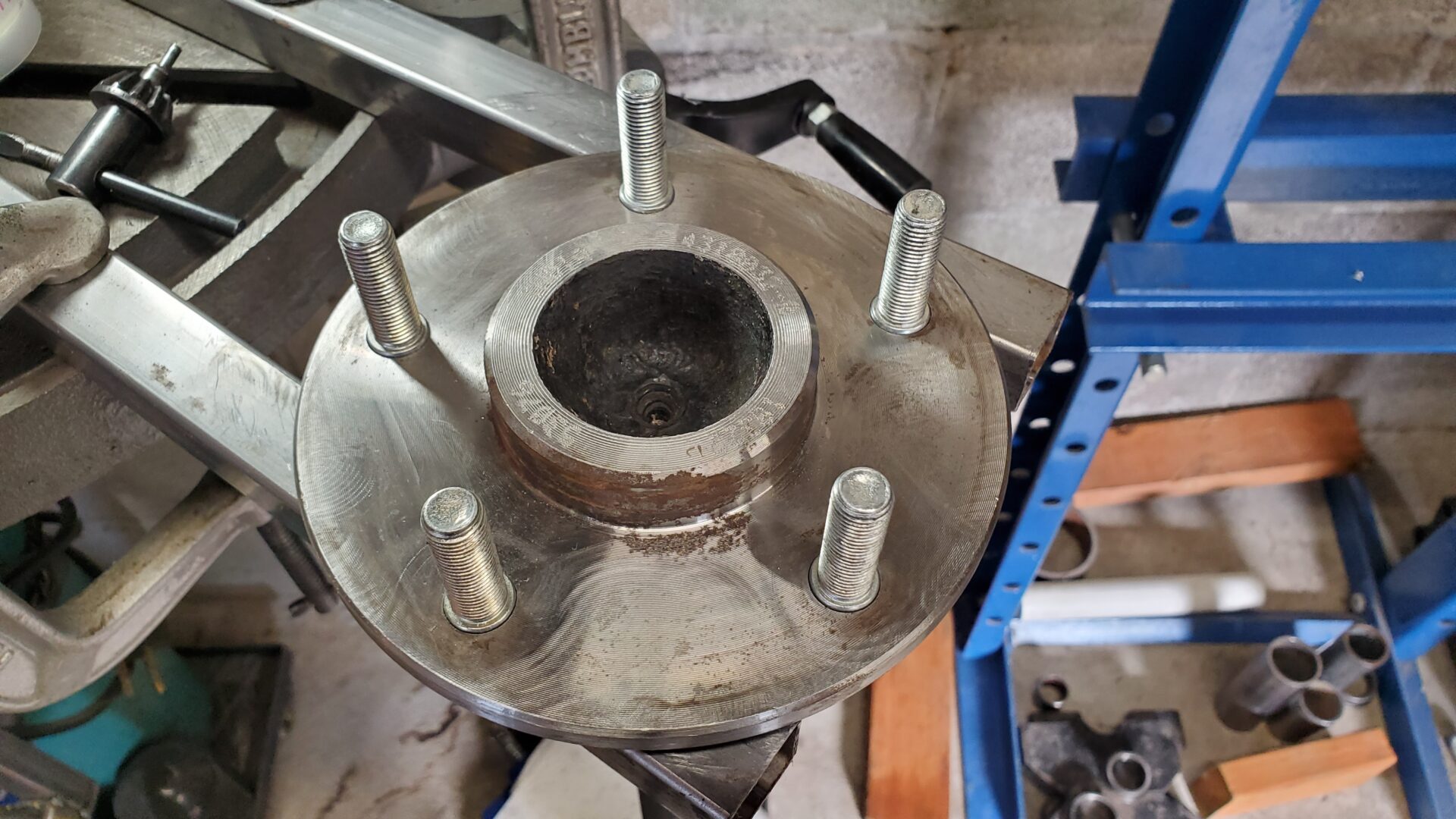
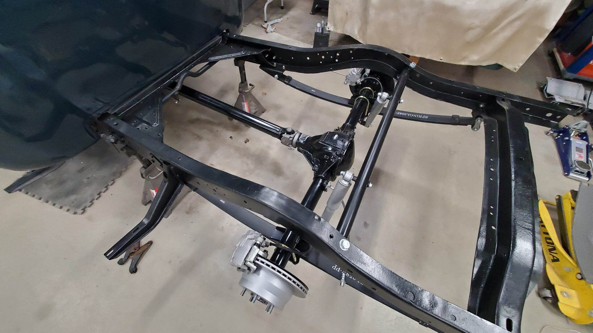
The axle housing is a little lighter and easier to handle without the axle shafts and brakes in places. So, it's bolted back onto the leaf springs and we proceed with brakes.
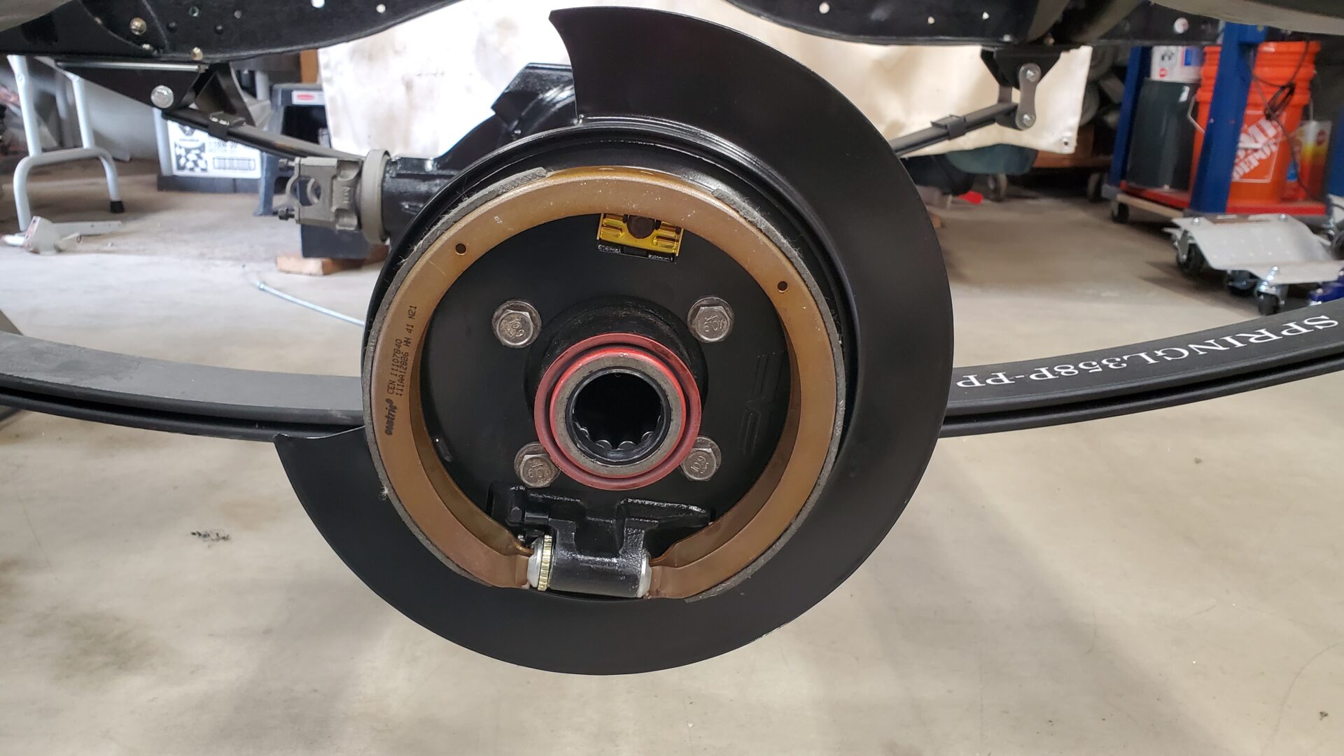
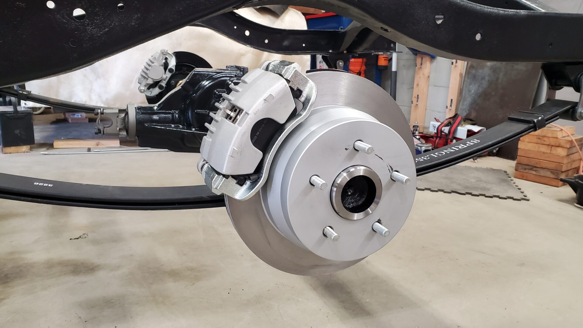
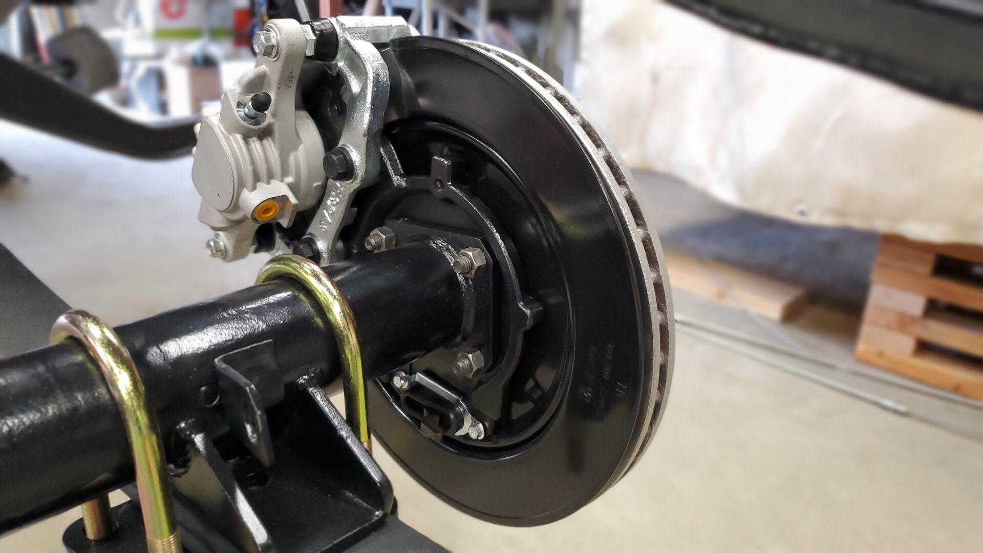
New brake hoses finish things off. Then the crossmember, and shock absorbers go on to complete the rear suspension. All that's left really is to run metal lines from the master cylinder to each wheel. Some compatible e-brake cables are also on the to-do list.
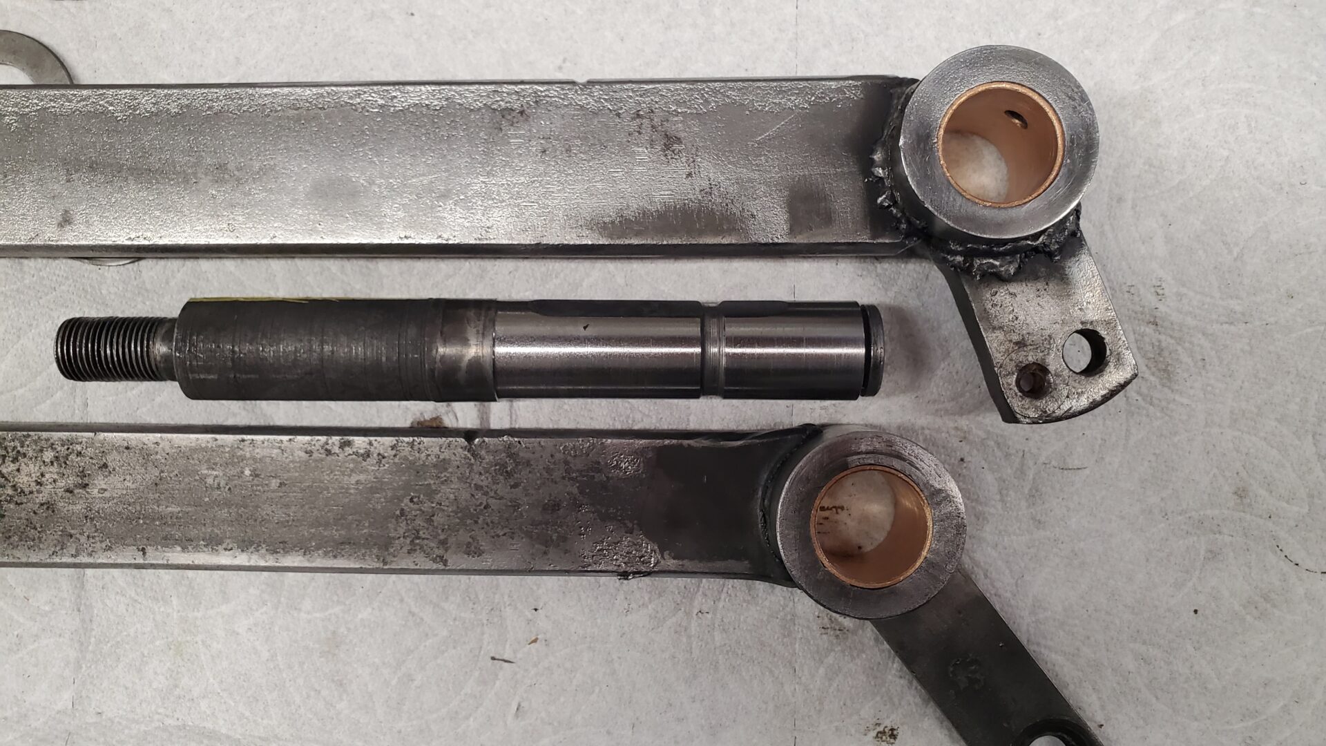
A couple of months ago, while restoring the the stock brake/clutch pedal assembly from the donor chassis, we took the pedal pivot shaft to a machine shop to have it turned on a lathe and true it up. It was badly worn in a couple of spots from years of use. The wear allowed the pedal arms to twist. Oversized brass bushings in each pedal arm take up the new clearance and allow them to pivot without the upper pedals rubbing the holes in the cab floor.
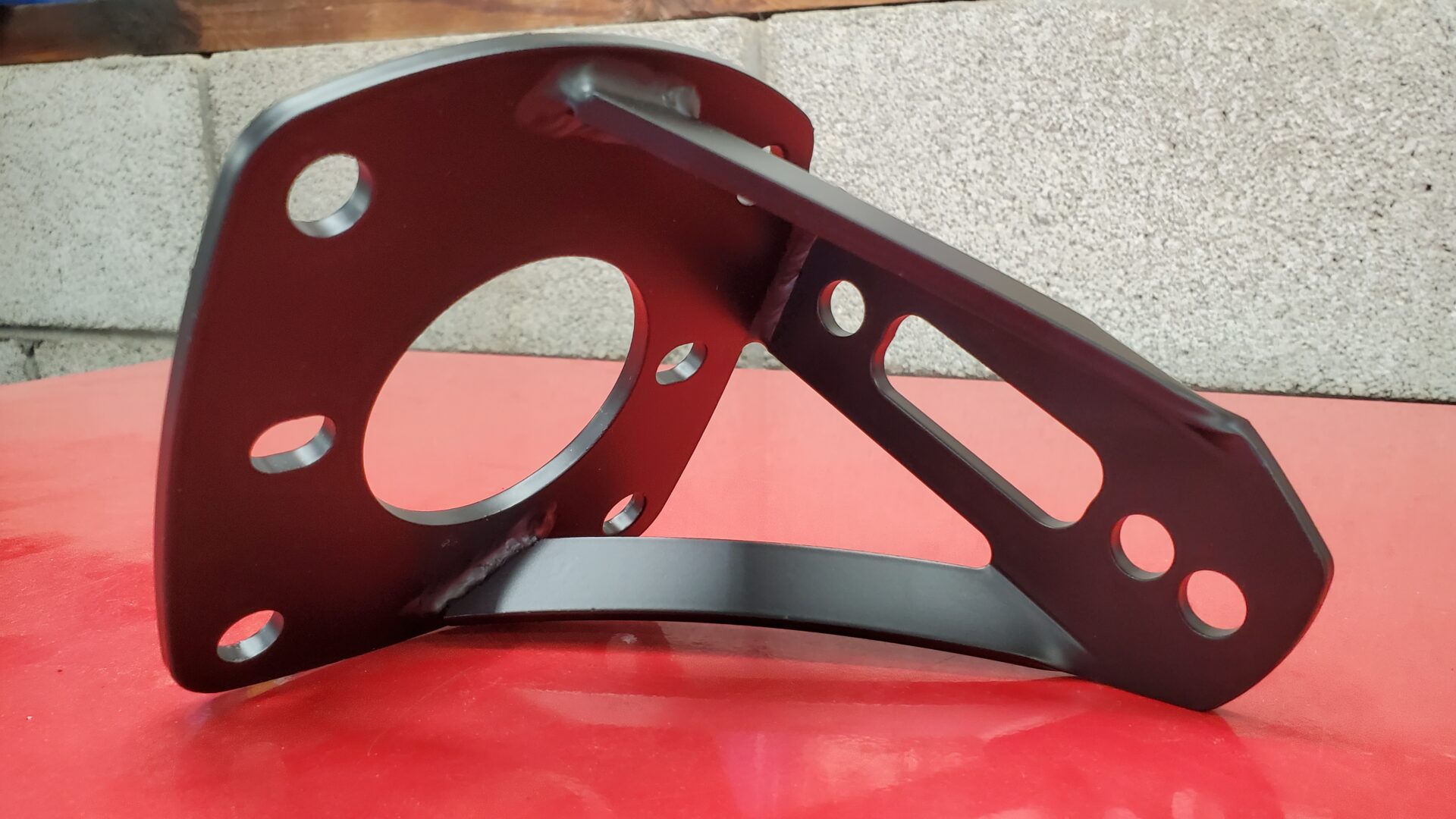
The brake master cylinder (and booster) that came in with the truck was another area that needed to be addressed. Someone had made a bracket to mount everything under the cab floor but it just didn't work for either position or function.
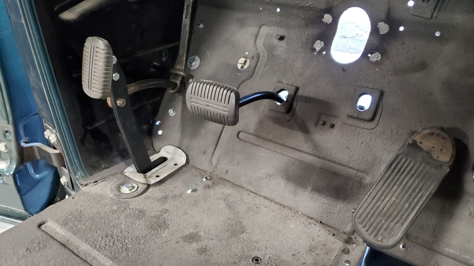
Our restored brake/clutch pedal assembly from the donor chassis was bolted to the frame for mockup. The clutch pedal works great but the brake pedal needs a little modification. From the factory it comes through the floor higher and sticks out further in an 'awkward' position. Our plan it to shorten it a good inch so that it lines up with the clutch pedal better and you don't have to bring your knee to chest to operate it.
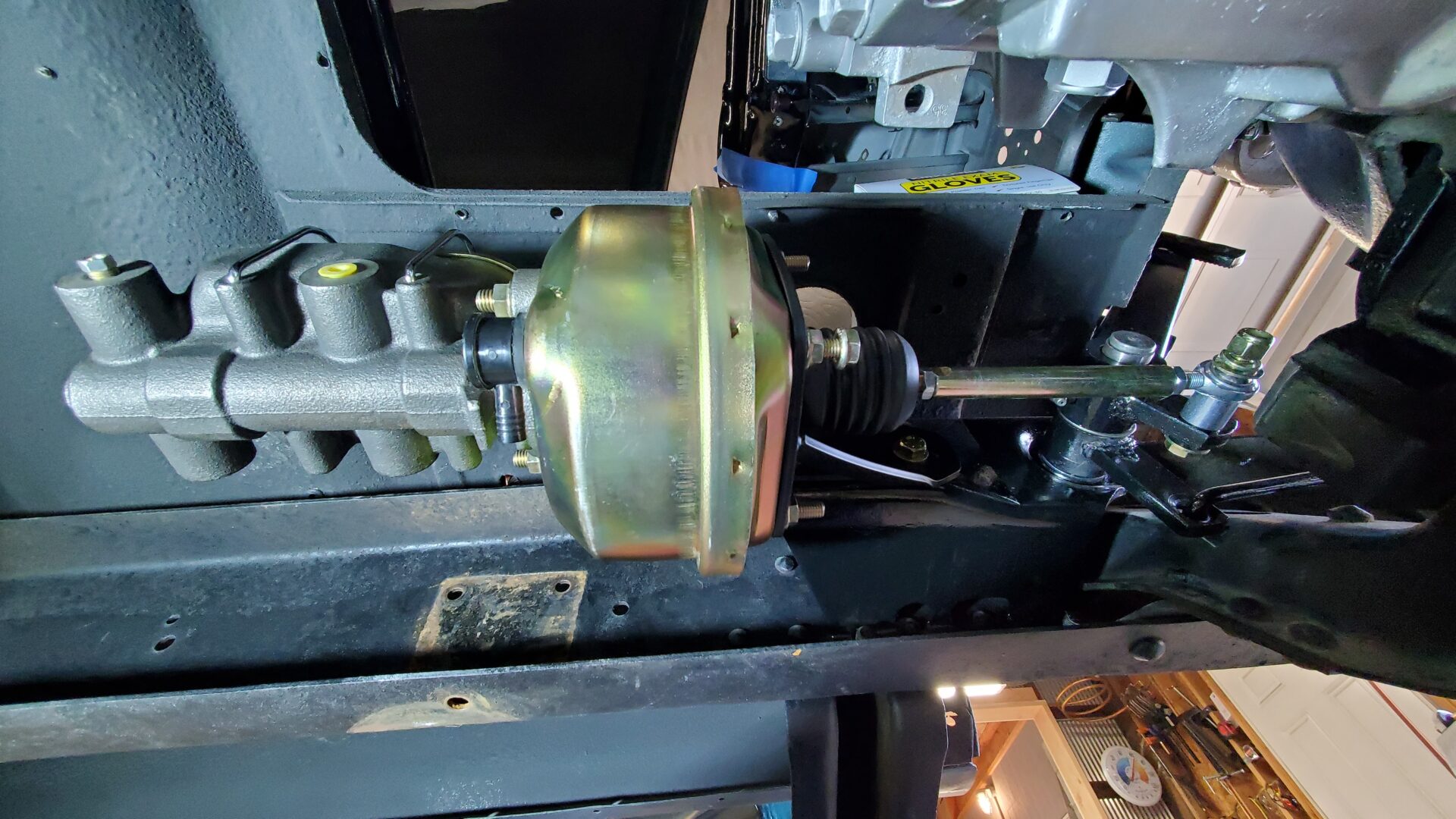
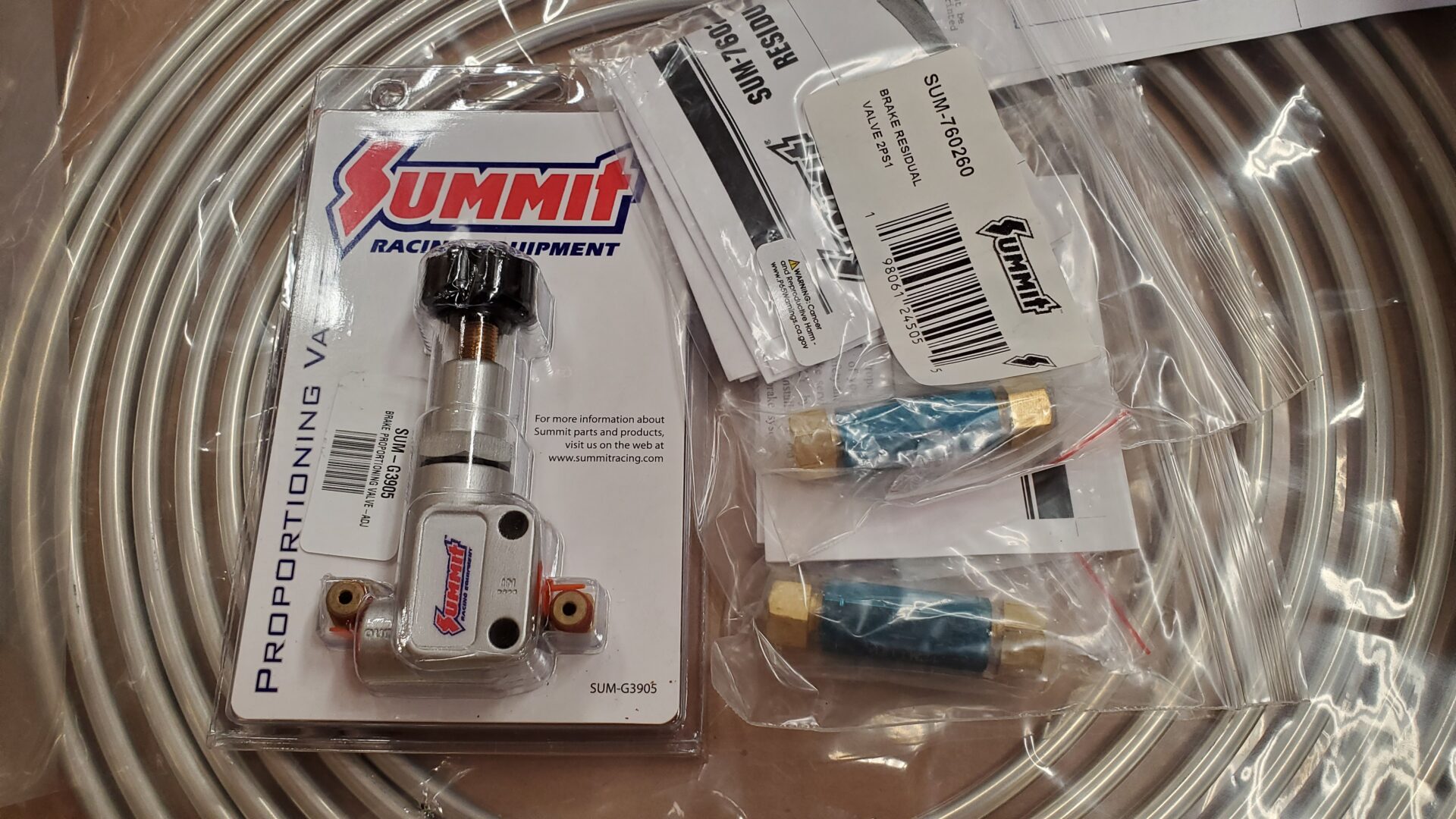
Since the master cylinder is under the cab floor and the brake calipers potentially higher, we will add residual pressure valves to the lines and an adjustable proportioning valve to our plumbing. This will prevent fluid drain back to the master and allow us to adjust braking bias between the front and rear.
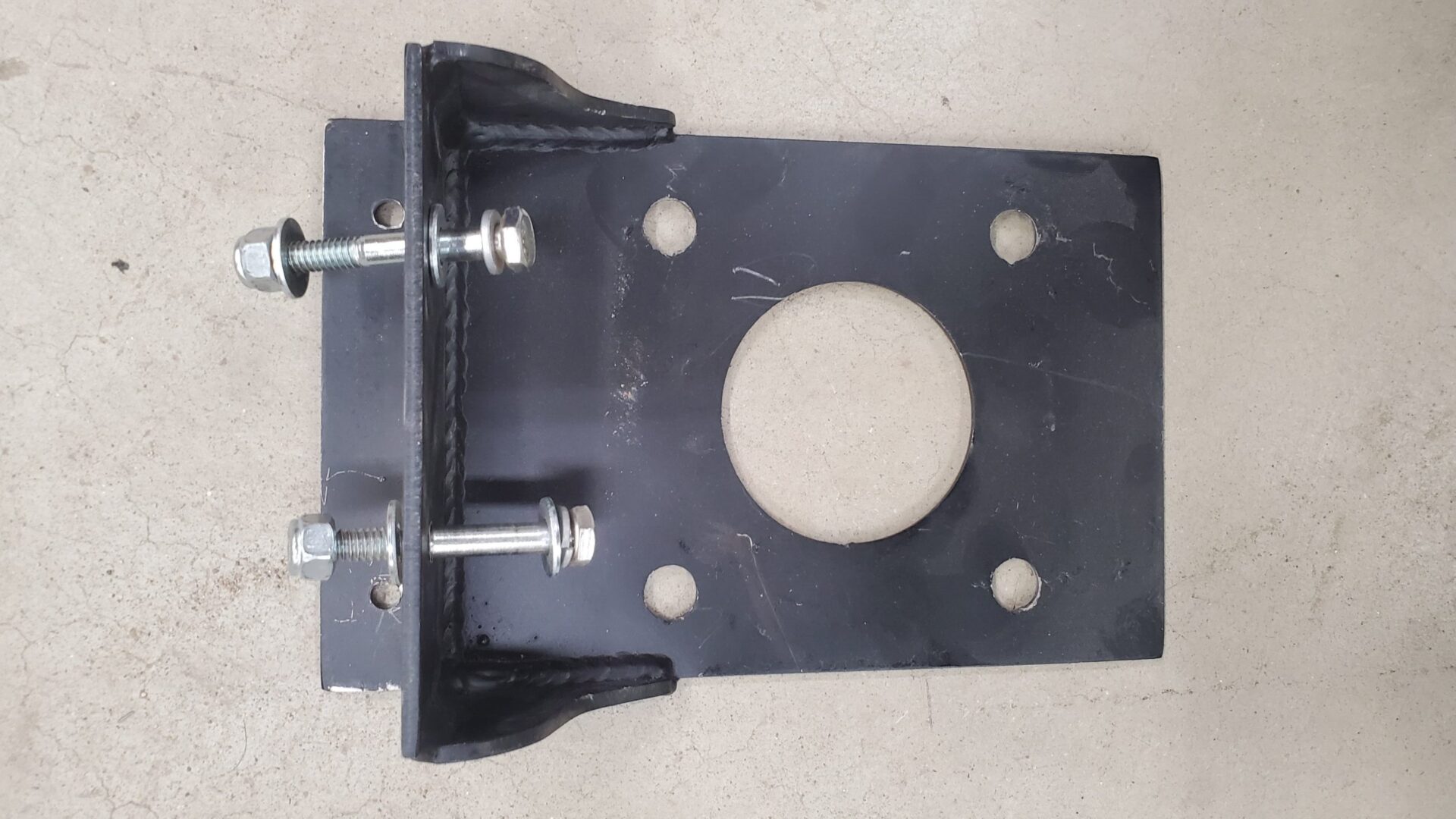
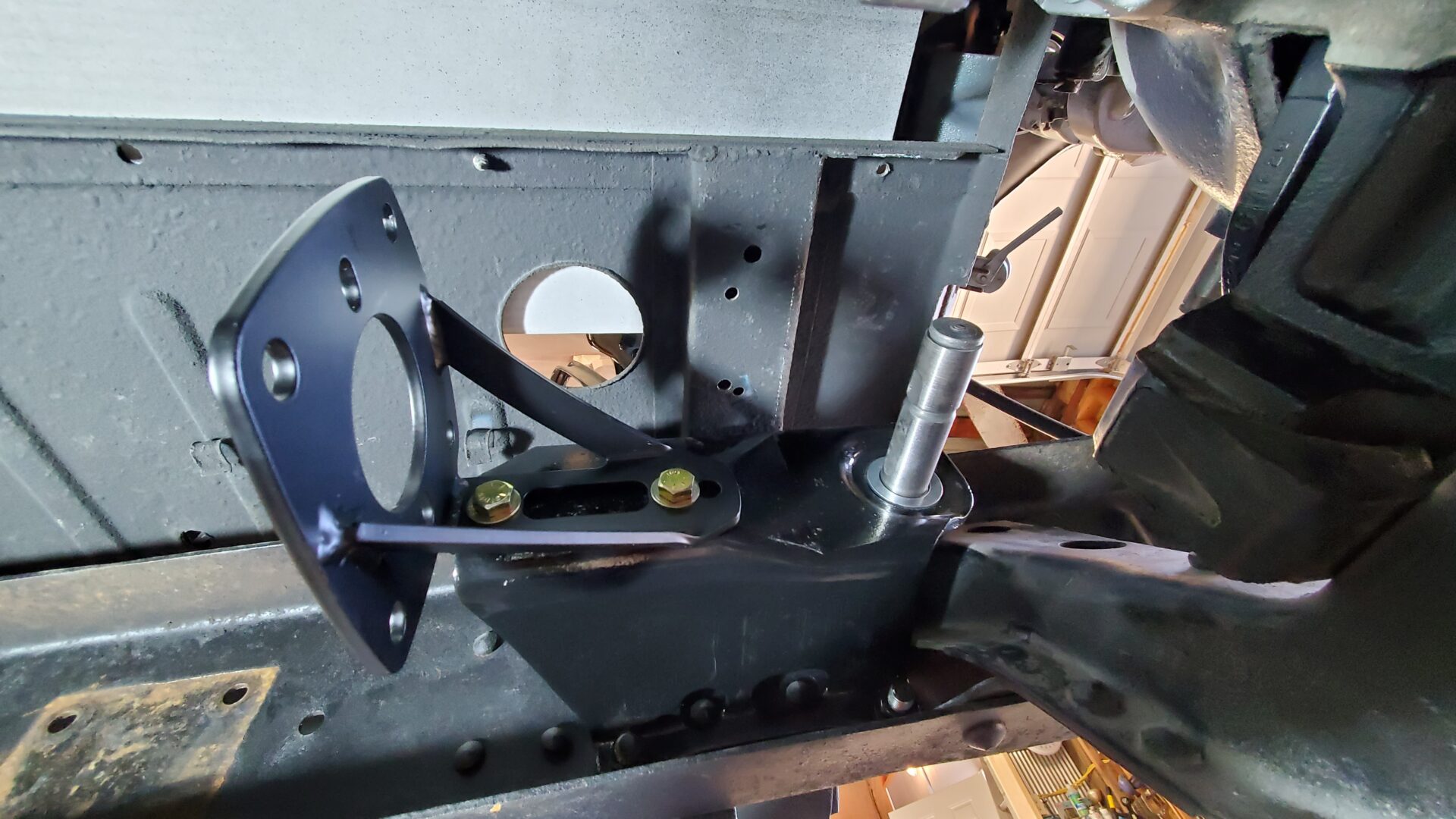
The parking or 'e-brake' on these old trucks is a very mechanical, 'Rube Goldberg'-like design. We found a rusty mounting bracket in a box along with a few pieces of the pedal assembly. Wiring was routed where it normally resides so we assume someone had other plans, or just didn't know what to do with it. The bracket also provides a mounting point for the inner fender on this side, so it's important.
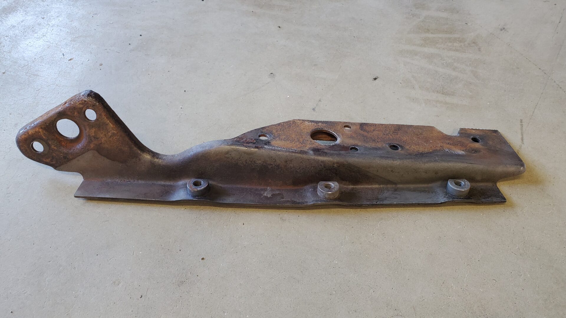
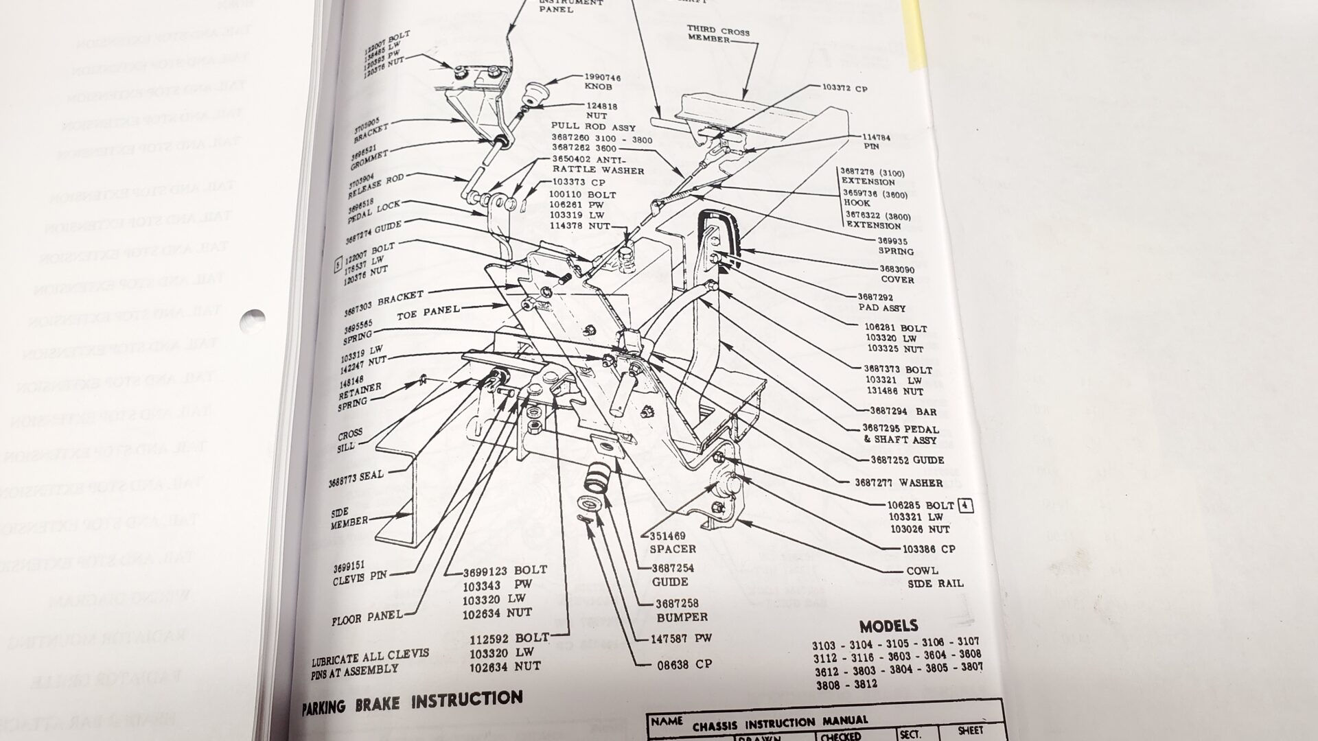
An assembly manual for these trucks (nothing but factory drawings but a valuable asset when sorting old vehicle puzzles) has an illustration showing how the whole thing goes together. Using this we were able to determine what was missing and acquire the bits.
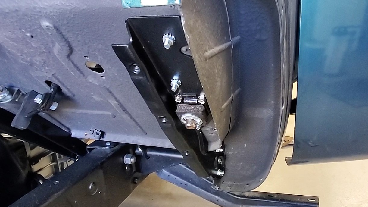
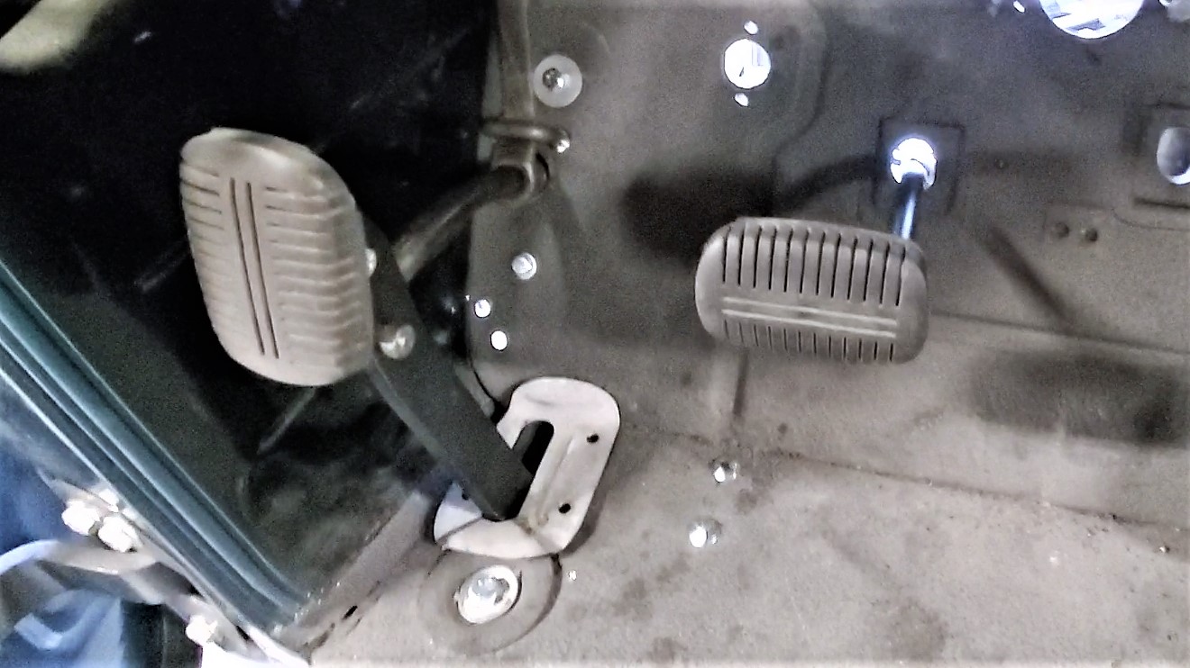
A long rod runs from the bottom of the pedal arm back to a cross shaft between each frame rail, just under and behind the cab. The steel rod was found in a box all wadded up into a ball. We straightened it out but that's why it still looks a little 'wiggly'. The big return spring came from our donor chassis.
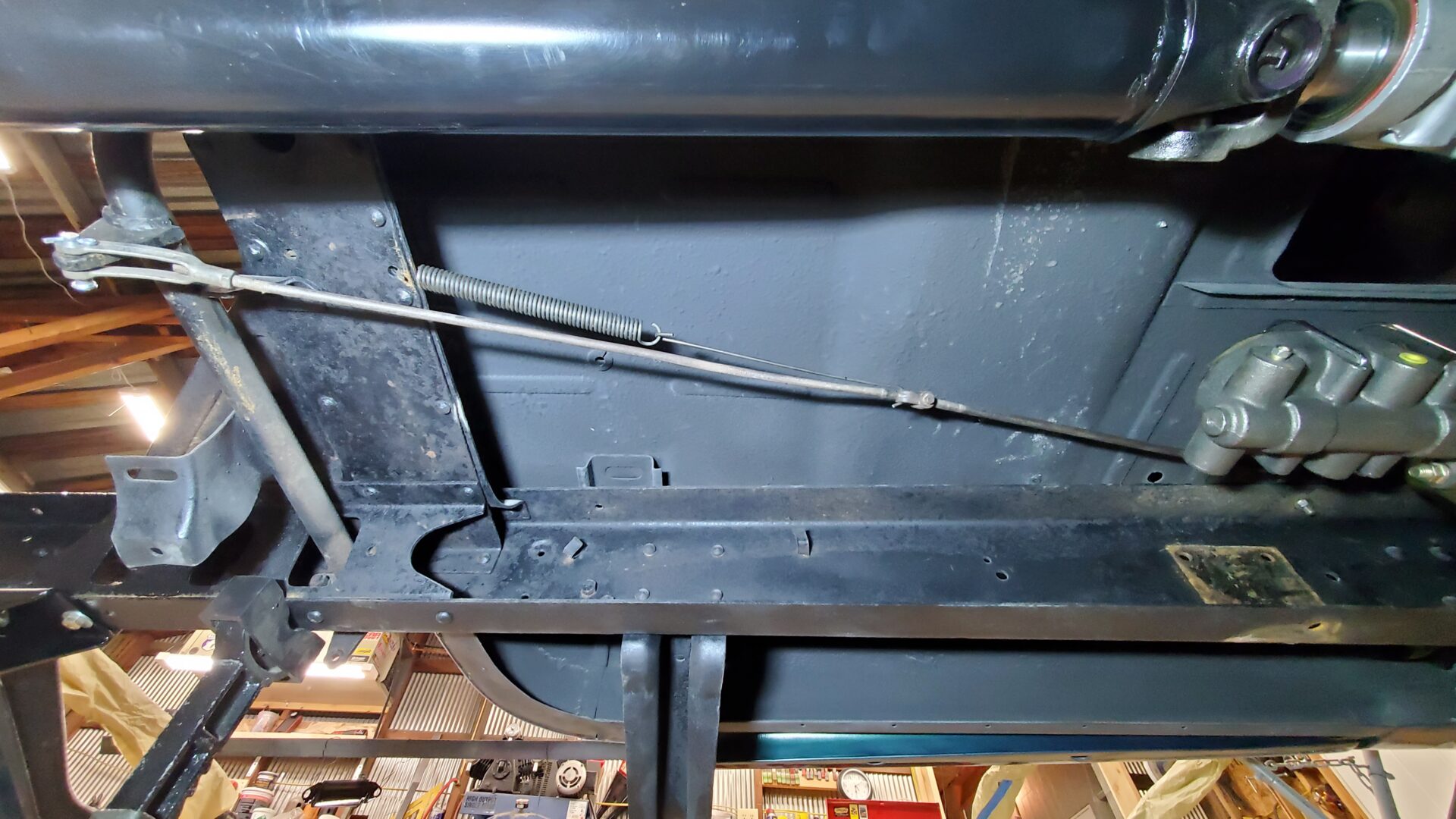
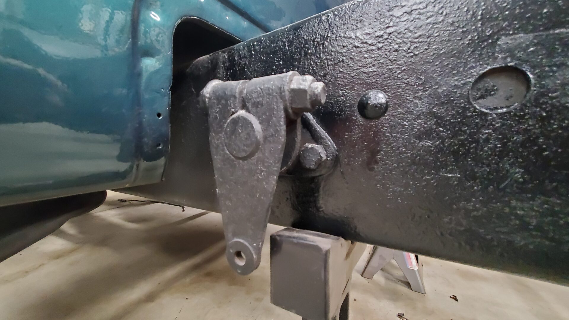
When the pedal is depressed in the cab, the rod pulls on the cross shaft, which, in turn, rotates levers at each end of the cross shaft, which pull cables that go to each rear wheel and apply the brake. On our new axle, the cables will expand the drum shoes inside the rotor hat pictured earlier.
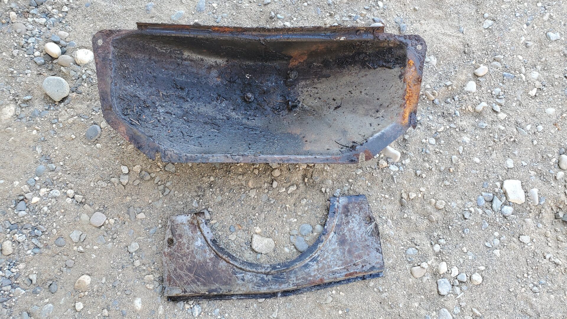
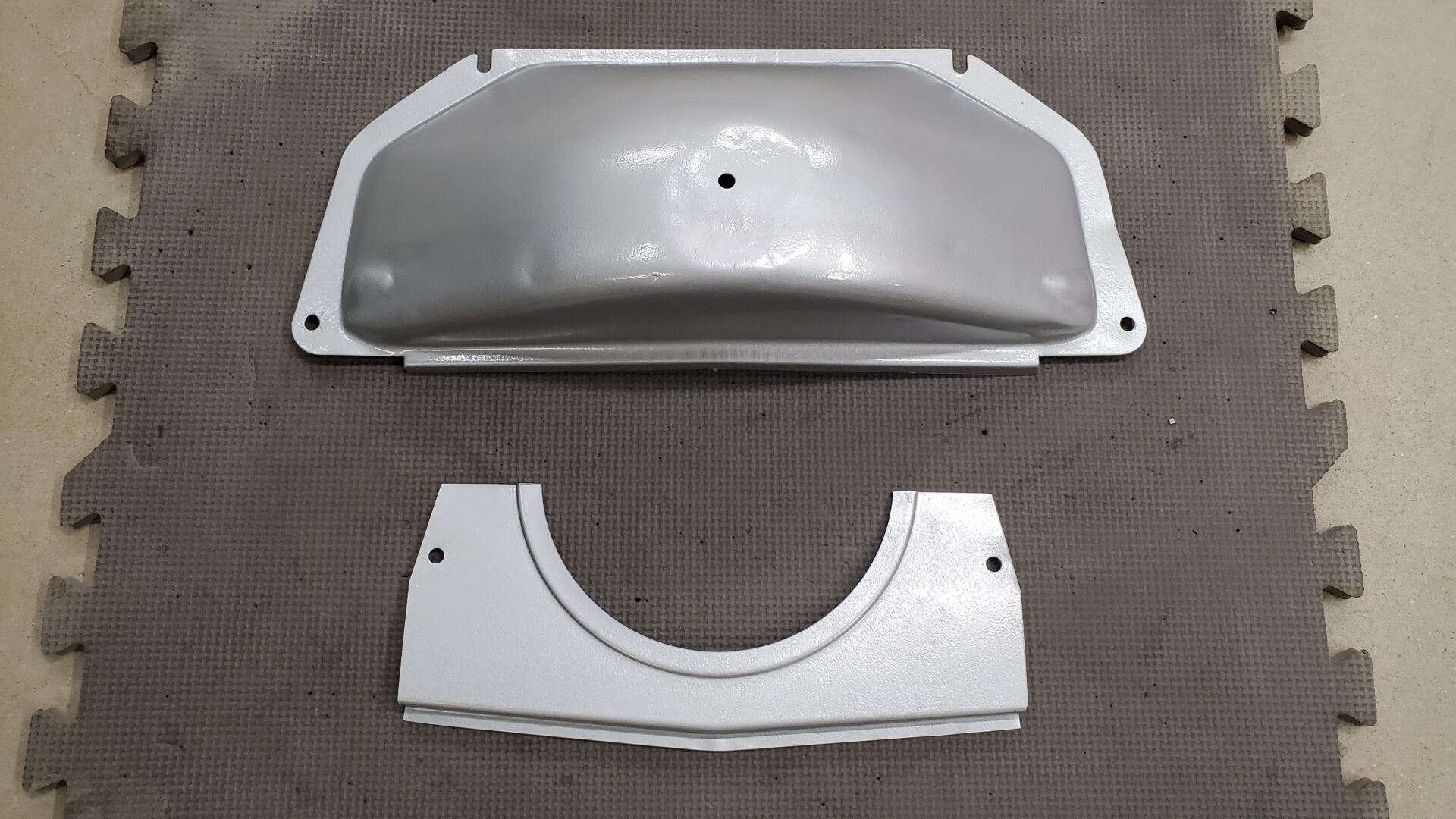
Details often make a subtle difference. A lot of times on these old trucks, when routine service work was done long ago, parts were removed and never put back on - then lost. In our case, the inspection covers for the clutch and flywheel at the bottom of the bell housing were long gone. They serve a practical purpose. Our donor chassis with engine (surprisingly) still had them in place. Yay!
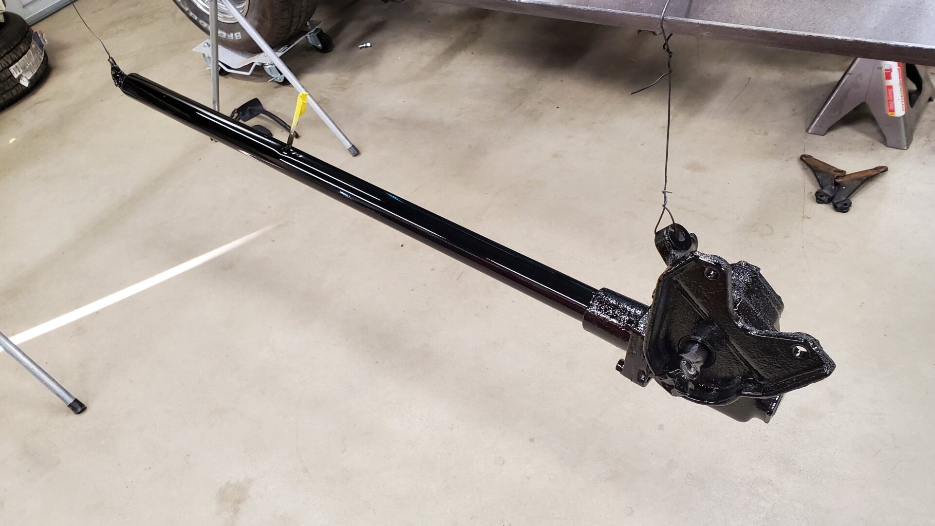
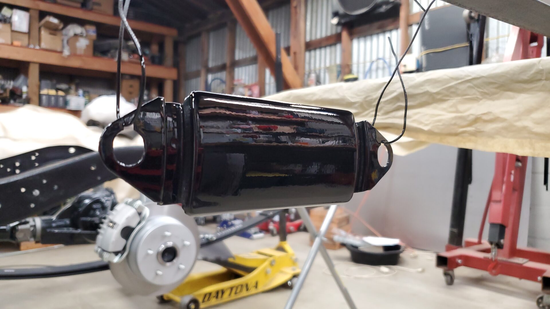
And finally, with temperatures quickly dropping we try to get a little automotive painting done - in this case our restored steering column with gear box and radio delete plate (both gloss black) to match the already painted interior.
Without a dedicated paint booth we popped outside for convenience. Naturally, when it was time to lay down the single stage urethane, the wind kicked up to a blustery level. Not what you want but we got through it and, of course, as soon as we were done the wind died completely. Almost on cue, tiny gnats were attracted to the sweet smelling, sticky finish. The pieces were quickly moved indoors to cure and they look great.
